Elastic inner expansion automatic clamp

An internal expansion and fixture technology, applied in the direction of clamping, manufacturing tools, supports, etc., can solve the problems of roundness deformation of inner holes, unguaranteed radial jumps of machined parts, severe problems, etc., to achieve sufficient clamping and ensure processing quality. Effect

Active Publication Date: 2018-01-19
安庆工匠智能化设备制造有限公司
View PDF6 Cites 0 Cited by
  • Summary
  • Abstract
  • Description
  • Claims
  • Application Information

AI Technical Summary

Problems solved by technology

The earliest internal three-jaw anti-expansion tooling fixture has been basically eliminated. The main disadvantage of this kind of fixture is that the force point is on the three jaws. After the processing is completed, due to the elastic deformation of thin-walled parts, the roundness of the inner hole will be reduced. The deformation was so severe that it could not meet the requirements of the product drawing at all, and it was replaced by an internal expansion fixture
The existing internal expansion fixture adopts the contact tensioning method of the entire inner hole, but in the actual use process, it is found that because the elastic expansion sleeve can rotate freely, and its elastic wall is quite thin, the effective supporting force is not very large, especially The reason is that the radial force generated during grooving is relatively large, which will cause the radial runout of the processed parts to be generally unable to be guaranteed

Method used


Image

  • Elastic inner expansion automatic clamp
  • Elastic inner expansion automatic clamp
  • Elastic inner expansion automatic clamp

Examples


Embodiment Construction

[0024] The preferred embodiments of the present invention will be described in detail below with reference to the accompanying drawings.

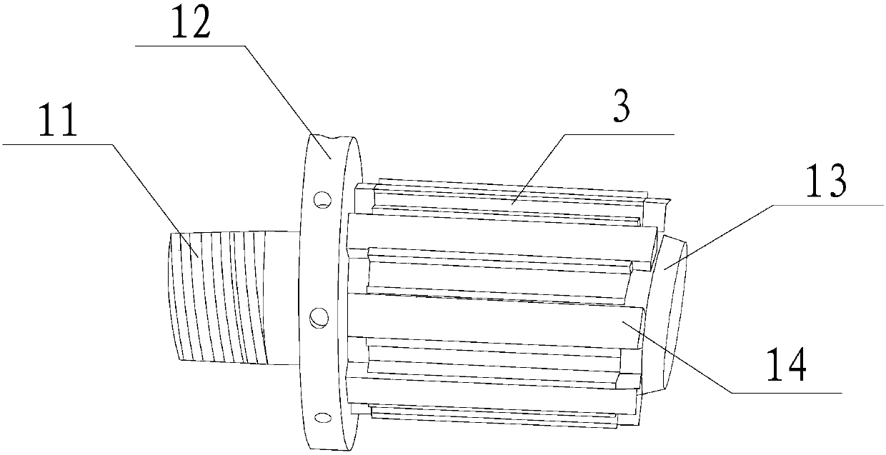
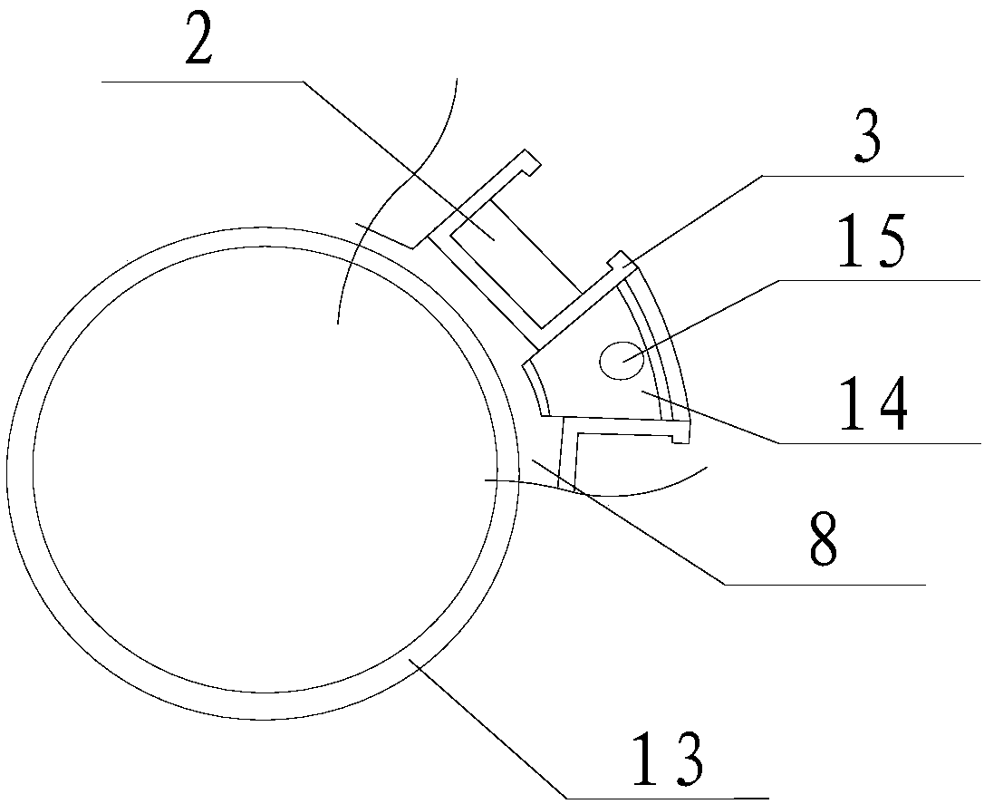
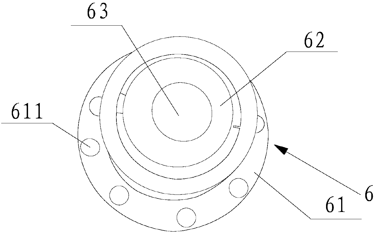
[0025] Such as Figure 1 to Figure 5 The shown elastic internal expansion automatic clamp mainly includes a clamp body 1, an elastic block 2, a support body 3, a spacer 4, a support plate 5 and a flange assembly 6 and other components.

[0026] Wherein, the clamp body 1 mainly includes a fixing part 11, a mounting part 12, a clamping part 13 and a protrusion 14, the mounting part 12 is arranged at the end of the fixing part 11; Hollow cylindrical structure; there are multiple protrusions 14, which are arranged at equal intervals on the peripheral surface of the clamping portion 13, and first fixing holes 15 are embedded in them. The support body 3 is detachably installed between two adjacent protrusions 14. In this embodiment, an accommodating space 31 communicating with the outside is formed in the support body 3, so that the elastic bloc...


PUM


Abstract

The invention relates to an elastic internal expanding type automatic clamp which comprises a clamp body, supporting bodies, an expanding body, elastic blocks, a plurality of spacers, a plurality of supporting pieces and a flange assembly, wherein the clamp body comprises a fixing part, an installing part arranged at the end part of the fixing part, a hollow cylindrical clamping part mounted on the end face of the installing part, and a plurality of convex blocks arranged on the circumferential surface of the clamping part at intervals; each supporting body is detachably mounted between every two adjacent convex blocks; the expanding body is arranged on the circumferential surface of the clamping part; the elastic blocks are detachably mounted in the supporting bodies; each spacer is arranged between the elastic block and the corresponding supporting body; each supporting piece is clamped between the elastic block and the corresponding supporting body; every two adjacent supporting pieces are separated by at least one spacer; the flange assembly is detachably arranged at the end parts of the convex blocks. The elastic internal expanding type automatic clamp can fully clamp a part to ensure the machining quality of the part.

Description

technical field [0001] The invention relates to an automatic clamp, in particular to an elastic internal expansion automatic clamp. Background technique [0002] With the continuous improvement of machining accuracy, the requirements for tooling and fixtures for parts processing are also getting higher and higher, especially for the processing of thin-walled cylindrical parts. The earliest internal three-jaw anti-expansion tooling fixture has been basically eliminated. The main disadvantage of this kind of fixture is that the force point is on the three jaws. After the processing is completed, due to the elastic deformation of thin-walled parts, the roundness of the inner hole will be reduced. The deformation was so severe that it could not meet the requirements of the product drawings at all, and it was replaced by an internal expansion fixture. The existing internal expansion fixture adopts the contact tensioning method of the entire inner hole, but in the actual use proc...

Claims


Application Information

Patent Timeline
Patent Type & Authority Patents(China)
IPC IPC(8): B23Q3/14B23Q3/06
CPCB23Q3/067B23Q3/14
Inventor 洪宗禹
Owner 安庆工匠智能化设备制造有限公司
Why Eureka
Try Eureka