Fast valve with controllable damping structure

A damping structure, fast technology, applied in the direction of valve details, valve device, valve operation/release device, etc., can solve the problems of small valve core mass, small impact force of valve body, unable to meet application requirements, etc., and achieve strong damping effect , the effect of cushioning the impact

Inactive Publication Date: 2016-09-21
INHALE HYPERSONIC TECH RES CENT UNIT 63820 OF PLA
View PDF5 Cites 6 Cited by
  • Summary
  • Abstract
  • Description
  • Claims
  • Application Information

AI Technical Summary

Problems solved by technology

However, when the above-mentioned quick valve is used in a large-caliber effective diameter application environment (for example, a 200mm caliber quick valve), there are deficiencies. The main reason is that the small-caliber quick valve spool has a small mass, and when the valve is opened quickly, the piston exerts pressure on the valve body. The impact force is small, and the conventional rubber cushion can meet the requiremen

Method used


Image

  • Fast valve with controllable damping structure
  • Fast valve with controllable damping structure
  • Fast valve with controllable damping structure

Examples


Embodiment Construction

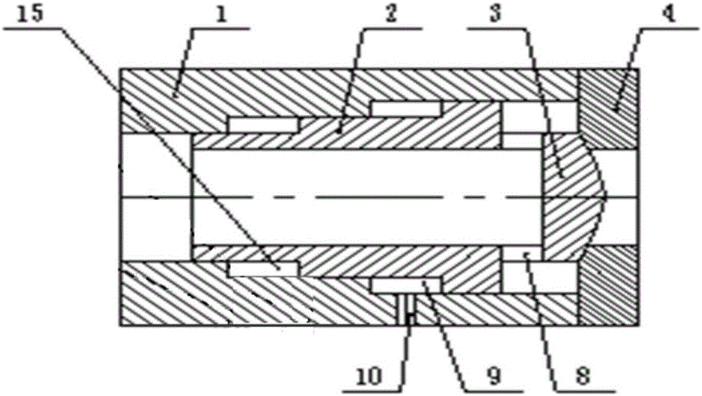
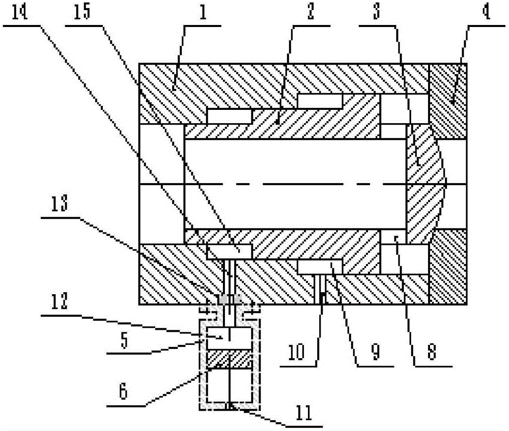
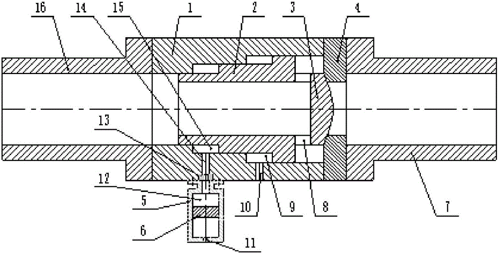
[0017] A fast valve with controllable damping structure, its structure is as follows figure 2 As shown, it includes a tubular valve body 1, a tubular piston 2, a valve core 3 and an end cover 4; the tubular piston 2 is set inside the tubular valve body 1 and can slide left and right; Connected, a radial channel hole 8 is provided between the valve core 3 and the right end surface of the tubular piston 2, a driving air chamber 9 and a damping chamber 15 are respectively provided between the tubular piston 2 and the tubular valve body 1, and the tubular valve body 1 A drive air chamber charging and deflation port 10 communicating with the driving air chamber 9 and a damping liquid through hole 14 communicating with the damping chamber 15 are respectively provided on the top. The fast valve with a controllable damping structure also includes a controllable damping structure, and the controllable damping structure includes a throttling orifice 13, a damping cylinder 5 and a dampi...


PUM


Abstract

The invention provides a fast valve with a controllable damping structure, which belongs to the technical field of pulse combustion wind tunnels. The present invention adds a controllable damping structure on the basis of the existing fast valve, and the controllable damping structure includes a throttle orifice, a damping liquid cylinder and a damping liquid cylinder piston; the damping liquid cylinder piston divides the damping liquid cylinder into an upper damping liquid cavity and the lower driving air chamber, the lower driving air chamber is connected to the driving air source through a filling and discharging hole, the upper damping liquid chamber communicates with the damping chamber through the throttling hole on the throttle orifice plate, and the damping liquid through hole; the damping chamber and the upper damping chamber The liquid cavity is filled with damping liquid. The present invention realizes the adjustment of the opening speed of the entire fast valve by adjusting the aperture size of the throttle hole on the throttle orifice 13 in the controllable damping structure, and at the same time adopts the liquid damping method to more effectively buffer the piston during the valve opening process. The impact on the valve body can meet the application requirements of building a larger pulse combustion wind tunnel project.

Description

technical field [0001] The invention belongs to the technical field of pulse combustion wind tunnels, in particular to a fast valve for pulse combustion wind tunnels. Background technique [0002] Pulse combustion wind tunnels are widely used in the field of air-breathing hypersonic research, and have the advantages of low construction and operation costs, simple systems, convenient maintenance, and short construction periods. The fast valve is one of the key devices to realize the pulsed combustion wind tunnel. It is mainly used for the rapid supply of gas, and has the characteristics of fast response time and fast opening speed (millisecond level). [0003] In the 11th National Shock Wave and Shock Tube Academic Conference "Development of Large-diameter Fast Valve Synchronous Valve in 450mm Pulse Combustion Wind Tunnel", Tan Yu and others disclosed a fast valve with an effective diameter of 53mm. The quick valve structure is as figure 1 As shown, it is mainly composed of...

Claims


Application Information

Patent Timeline
IPC IPC(8): F16K31/122F16K47/02
CPCF16K31/122F16K47/023
Inventor 刘伟雄谭宇毛雄兵曾令国李宏斌任虎蒲旭阳林其伍军熊鹏飞翟小飞
Owner INHALE HYPERSONIC TECH RES CENT UNIT 63820 OF PLA
Why Eureka
Try Eureka