Check patentability & draft patents in minutes with Patsnap Eureka AI!
A waterproof electric thermal insulation joint
What is Al technical title?
Al technical title is built by PatSnap Al team. It summarizes the technical point description of the patent document.
An electrothermal fusion and waterproof technology, applied in the direction of pipes/pipe joints/fittings, pipe connection arrangements, non-removable pipe connections, etc. problems, to achieve the effect of improving construction quality, low preparation cost and reasonable structure
Active Publication Date: 2019-04-02
华电青岛热力有限公司 +1
View PDF7 Cites 0 Cited by
Summary
Abstract
Description
Claims
Application Information
AI Technical Summary
This helps you quickly interpret patents by identifying the three key elements:
Problems solved by technology
Method used
Benefits of technology
Problems solved by technology
At present, when direct-buried thermal insulation pipelines are laid in areas with rich groundwater, if any part of the pipeline system is damaged from the outside, causing groundwater to enter the pipeline insulation system, the vaporization of water at high temperature will accelerate the carbonization of the polyurethane insulation layer and make it invalid, and the groundwater will directly When in contact with the steel pipe, more heat will be transferred outward and cause corrosion on the outer surface of the pipe. The high-temperature medium in the pipe will heat more groundwater, form more steam, and extend to both ends more quickly, destroying more The polyurethane insulation layer formed a vicious circle, which will eventually lead to the failure of the insulation of the entire pipeline and the corrosion of the working steel pipe by groundwater, which will bring huge economic losses and safety hazards that cannot be ignored to the heating enterprises.
In the pipeline system, the insulation pipe is generally prefabricated in the factory, and the quality is relatively easy to guarantee; while the joint insulation needs to be made on the construction site, affected by many actual construction conditions, the insulation joint is far less firm than the prefabricated insulation pipe, and becomes a heating pipe. The short board of the system
Method used
Image
Click on the blue label to locate the original text in one second.
Reading with bidirectional positioning of images and text.
Examples
Embodiment
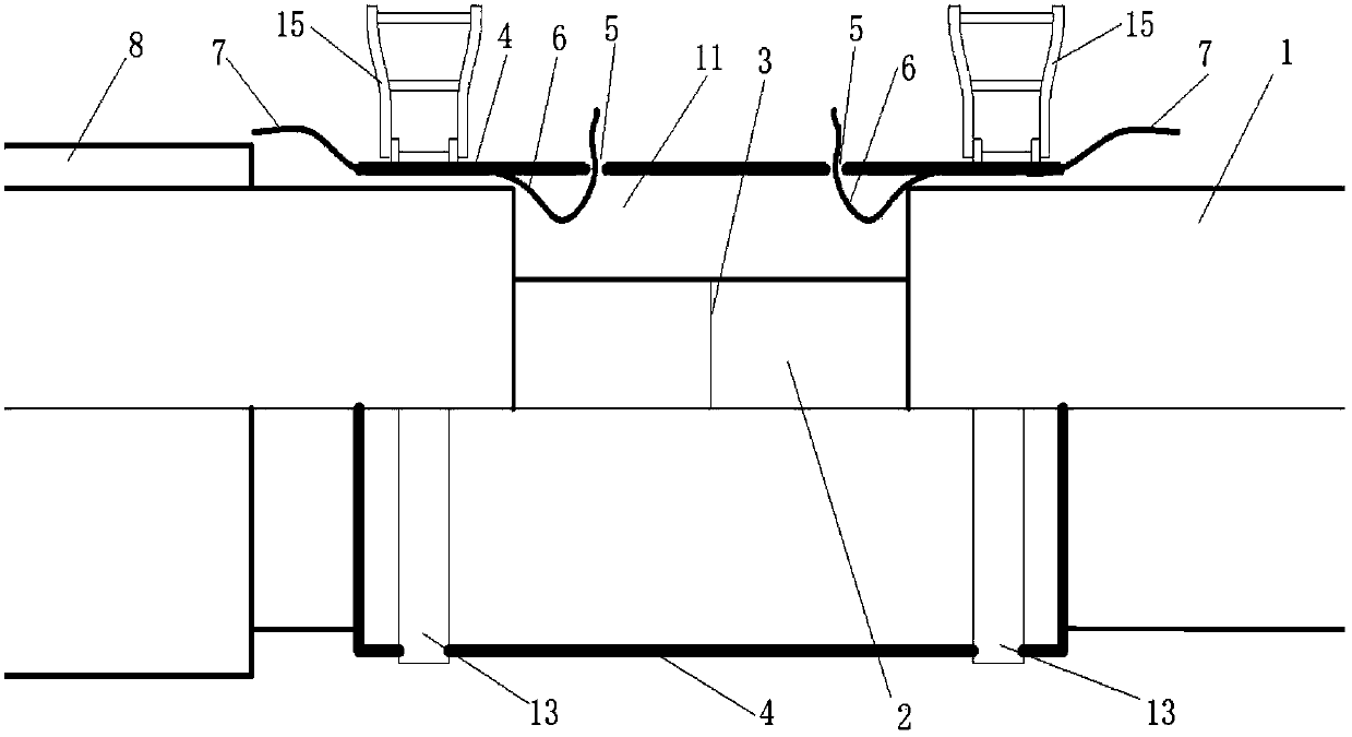
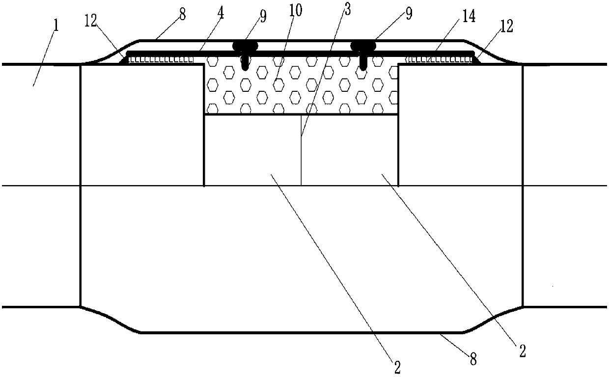
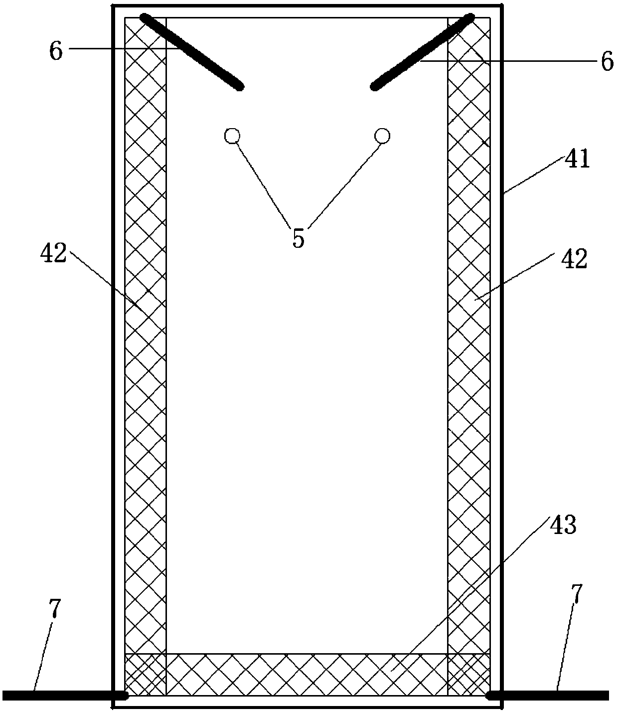
[0021] The main structure of the waterproof electric thermal insulation joint involved in this embodiment includes a PE shell 1, a steel pipe 2, a steel pipe weld 3, an electric thermal sleeve sleeve 4, a material injection port 5, a primary heating cable 6, a secondary heating cable 7, Seam heat shrinkable sleeve 8, plug 9, polyurethane foam plastic 10, foam cavity 11, plastic welding 12, clamping belt 13, PE lap joint 14 and clamper 15; PE shell 1 of tubular structure is lined with a steel pipe 2. Welding connection between adjacent steel pipes 2; the ring-shaped electric heating sleeve 4 is wrapped on the outside of the PE shell 1, so as to seal the foaming cavity 11 formed between the electric heating sleeve 4, the PE shell 1 and the steel pipe 2; The overlap between the electric heating sleeve 4 and the PE shell 1 is welded and sealed by plastic welding 12 to form a PE overlapping seam 14; the electric heating sleeve 4 is provided with a material injection port 5 for injec...
PUM
Property
Measurement
Unit
radius
aaaaa
aaaaa
Abstract
The invention belongs to the technical field of heat supply and insulation and relates to an insulation joint for a directly-buried high-temperature hot-water pipe network in heat-supply engineering, in particular to a waterproof type electric hot-melting insulation joint. The waterproof type electric hot-melting insulation joint mainly comprises a PE casing, steel tubes, a steel tube weld seam, an electric hot-melting sleeve, charging ports, primary heating cables, secondary heating cables, a seamless thermal shrinkable sleeve, plugs, polyurethane foaming plastic, a foaming cavity, plastic welding, clamping straps, PE lap seams and clampers. The two sealing sleeves, namely the electric hot-melting sleeve and the seamless thermal shrinkable sleeve are arranged at the outer side of a pipeline, so that the sealing and water resisting properties of the insulation joint are enhanced; and by using two times of heating and welding for the electric hot-melting sleeve, in particular the secondary transverse joint heating, the construction quality of projects is further improved, and great significance for improving the construction quality of an insulation pipeline is realized. The waterproof type electric hot-melting insulation joint has the advantages of simple principle, reasonable structure, low preparation cost, mature and safe mounting process, good application environment and wide application range.
Description
Technical field: [0001] The invention belongs to the technical field of heat supply and heat preservation, and relates to a thermal insulation joint for directly buried high-temperature hot water pipe networks in heating engineering, in particular to a waterproof electric thermal insulation joint, which is provided through an electric thermal fusion sleeve and an The seam heat shrinkable sleeve and the two sealing sleeves can ensure the sealing and waterproof performance of the thermal insulation joint, and the construction quality of the project can be further improved through the two times of heating and welding of the electric melting sleeve. Background technique: [0002] Since the introduction of Nordic prefabricated direct-buried thermal insulation pipes in my country in the 1980s, the construction technology of direct-buried heating and thermal insulation pipes in China has developed rapidly. Great progress; with the popularization of high-temperature hot water pipelin...
Claims
Application Information
Patent Timeline
Application Date:The date an application was filed.
Publication Date:The date a patent or application was officially published.
First Publication Date:The earliest publication date of a patent with the same application number.
Issue Date:Publication date of the patent grant document.
PCT Entry Date:The Entry date of PCT National Phase.
Estimated Expiry Date:The statutory expiry date of a patent right according to the Patent Law, and it is the longest term of protection that the patent right can achieve without the termination of the patent right due to other reasons(Term extension factor has been taken into account ).
Invalid Date:Actual expiry date is based on effective date or publication date of legal transaction data of invalid patent.
