Conductive contact and electric connector

A technology of conductive contact and connection section, applied in the direction of contact parts, etc., can solve the problem of large insertion loss, achieve the effect of reducing insertion loss and eliminating the radiation effect of short piles

Active Publication Date: 2016-09-21
CHINA AVIATION OPTICAL-ELECTRICAL TECH CO LTD
View PDF7 Cites 5 Cited by
  • Summary
  • Abstract
  • Description
  • Claims
  • Application Information

AI Technical Summary

Problems solved by technology

However, when this kind of contact is in the plugged state, the bent section of the male end is tilted upwards, resulting in the formation of a short pile radiation effect, resulting in a large insertion loss

Method used


Image

  • Conductive contact and electric connector
  • Conductive contact and electric connector

Examples


Embodiment Construction

[0016] Embodiments of the present invention will be further described below in conjunction with the accompanying drawings.

[0017] A specific embodiment of the conductive connector of the present invention includes a connector housing and a conductive contact piece disposed in the connector housing.

[0018] The electrical connector of the present invention realizes the conductive connection through the conductive contact between the conductive contact and the matching conductive contact in the matching electrical connector, wherein the matching conductive contact has the same structure as the conductive contact, and the difference is that the matching conductive The contact piece is opposite to the installation direction of the conductive connection piece in the vertical direction, and only the structure of the conductive contact piece will be described in detail below.

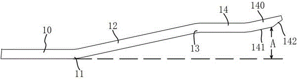
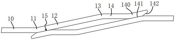
[0019] The structure of the conductive contact is as Figure 1-2 As shown, it includes a base body 10 e...


PUM


Abstract

The invention provides a conductive contact and an electric connector, wherein the conductive contact comprises a base body, the front end of the base body is connected with an upward sloping first connecting section through a first bending section, the front end of the first connecting section is connected with a contact section through a second bending section, a front contact part is arranged on the contact section, a front contact point which is used for contacting with an adaptive conductive contact is arranged on the front contact part, the lower side of the first connecting section comprises a rear contact point which is used for contacting with the adaptive conductive contact, an insertion space which is used for being inserted by the adaptive conductive contact is arranged between the front contact point and the base body in up-down direction, and an insertion guide surface which avoids abutting between the conductive contact and the adaptive conductive contact in insertion is arranged on the front side of the front contact point on the front contact part. According to the invention, the structure of the conductive contact is improved, so that the overhang structure of the front side of the conductive contact point and the short pile irradiation effect are eliminated, the conductive connection is realized through two-point contact, and the insertion loss is low.

Description

technical field [0001] The invention relates to a conductive contact piece and an electrical connector. Background technique [0002] Chip contacts are widely used in high-speed differential data transmission due to their simple structure and convenient characteristic impedance calculation. For example, the Chinese invention patent with application publication number CN105428939A and application publication date of 2016.3.23 discloses a conductive contact, an electrical connector and an electrical connector assembly. The conductive contact includes a male contact body, a male contact The contact body includes a male end contact section. The front end of the male end contact section is provided with a male end front contact portion protruding downward. The male end front contact portion includes a male end lower bend section and a male end upper bend section. The contact is located at the transition position between the lower bent section of the male end and the upper bent s...

Claims


Application Information

Patent Timeline
Patent Type & Authority Applications(China)
IPC IPC(8): H01R13/28
CPCH01R13/28
Inventor 周国奇赵越超袁俊峰
Owner CHINA AVIATION OPTICAL-ELECTRICAL TECH CO LTD
Why Eureka
Try Eureka