
A mechanical linkage group lightning arrester mechanism and its application method

A lightning arrester and mechanical technology, applied in the field of mechanically linked group arrester mechanism, can solve the problems of inability to realize the lightning arrester linkage operation, insufficient safety distance for staff, low work efficiency, etc. Effect

Active Publication Date: 2018-04-06
STATE GRID JIBEI ELECTRIC POWER CO LTD TANGSHAN POWER SUPPLY CO +1
View PDF10 Cites 0 Cited by
  • Summary
  • Abstract
  • Description
  • Claims
  • Application Information

AI Technical Summary

Problems solved by technology

In power transmission and distribution line equipment, the use of lightning arresters is essential, but the current installation technology of lightning arresters on transformer benches has great potential safety hazards. It is only about one meter away from the upper falling crossarm with 10KV voltage, which is far from enough for the safety distance of the staff, and it is very dangerous. In the past, it has happened that the staff held the measuring instrument with the 10KV high voltage wire by mistake. Fortunately, the guarded personnel stopped the incident in which the upper layer fell to the safety catcher; at the same time, the linkage operation of the entire set of arresters could not be realized, and the work efficiency was low. Now there is a need for a method that allows the staff to operate without the need of climbing poles and realize the linkage operation of the entire set of arresters arrester rack

Method used


Image

  • A mechanical linkage group lightning arrester mechanism and its application method
  • A mechanical linkage group lightning arrester mechanism and its application method
  • A mechanical linkage group lightning arrester mechanism and its application method

Examples


Embodiment Construction

[0020] The present invention will be further described below in conjunction with the drawings.

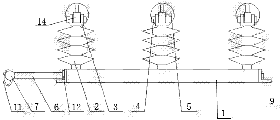
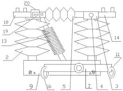
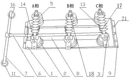
[0021] A mechanically linked group arrester mechanism and its use method, including arrester frame, insulator 2, swivel seat 3, spring clamping pin 4, arrester 5, rectangular through hole 8, grounding side contact seat 14, drop port Side contact seat 18, knife moving contact piece 19, and knife static contact piece 20; the arrester frame is a rectangular frame, including two arrester frame beams 1 and two arrester frame vertical beams 9, and two arrester frame beams 1 Arranged in parallel, two arrester frame vertical beams 9 are symmetrically arranged at the left and right ends of the two arrester frame beams 1, with rectangular through holes 8 in the middle; the insulators 2 are six, divided into three groups, and are arranged symmetrically and vertically in pairs. On the two arrester frame beams 1; the top of the three insulators 2 on the arrester frame beam 1 on one side of the rec...


PUM


Abstract

The invention and a mechanical linkage group arrester mechanism belong to the technical field of arresters for power supply systems. The technical solution is: the two ends of the interlock control rod (6) pass through two limit bearings (12) and are located in the rectangular through hole (8); the center part of the mechanical pull rod (7) is arranged horizontally and vertically On one side of the lock control rod (6), the two ends of the mechanical pull rod (7) are respectively provided with an opening pull ring (11) and a closing pull ring (16); the interlocking opening and closing support insulators (13) are three One, set directly below the three lightning arresters (5), the upper end is hinged with the knife moving contact piece (19), the lower end is hinged with one end of the lead angle connecting plate (17) through a pin shaft, and the other end of the lead angle connecting plate (17) ) are vertically welded on the interlock control rod (6). The invention has the advantages of simple structure, convenient installation, maintenance and replacement of the lightning arrester, easy manipulation, low cost, good safety performance, reduced accident rate and improved work efficiency.

Description

Technical field [0001] The invention relates to a mechanically linked group lightning arrester mechanism and a use method thereof, belonging to the technical field of lightning arresters for power supply systems. Background technique [0002] With the continuous development of society, the power network has covered most areas of our country, providing great convenience for people's production and life. In power transmission and distribution line equipment, the use of lightning arresters is indispensable, but the current installation technology of lightning arresters on transformer benches has great safety hazards. When measuring arresters on site, workers must board the transformer structure, and the arresters are cross-armed. The distance from the upper drop cross arm with 10KV voltage is only about one meter, which is far from enough for the safety of the staff and it is very dangerous. There have been cases in the past when the staff tried to misconnect the cable with the 10KV...

Claims


Application Information

Patent Timeline
Patent Type & Authority Patents(China)
IPC IPC(8): H02G13/00
CPCH02G13/00
Inventor 郑建兴
Owner STATE GRID JIBEI ELECTRIC POWER CO LTD TANGSHAN POWER SUPPLY CO
Features
  • Generate Ideas
  • Intellectual Property
  • Life Sciences
  • Materials
  • Tech Scout
  • Unparalleled Data Quality
  • Higher Quality Content
  • 60% Fewer Hallucinations
Learn More