On-line accurate measurement method of optical link loss in pon network
A technology for precise measurement and optical links, applied in electrical components, electromagnetic wave transmission systems, transmission systems, etc., can solve problems that cannot be used to judge the quality of optical fiber network links, improve quality management and quality control capabilities, and reduce external influences factors, the effect of improving calibration efficiency
- Summary
- Abstract
- Description
- Claims
- Application Information
AI Technical Summary
Problems solved by technology
Method used
Image
Examples
Embodiment 1
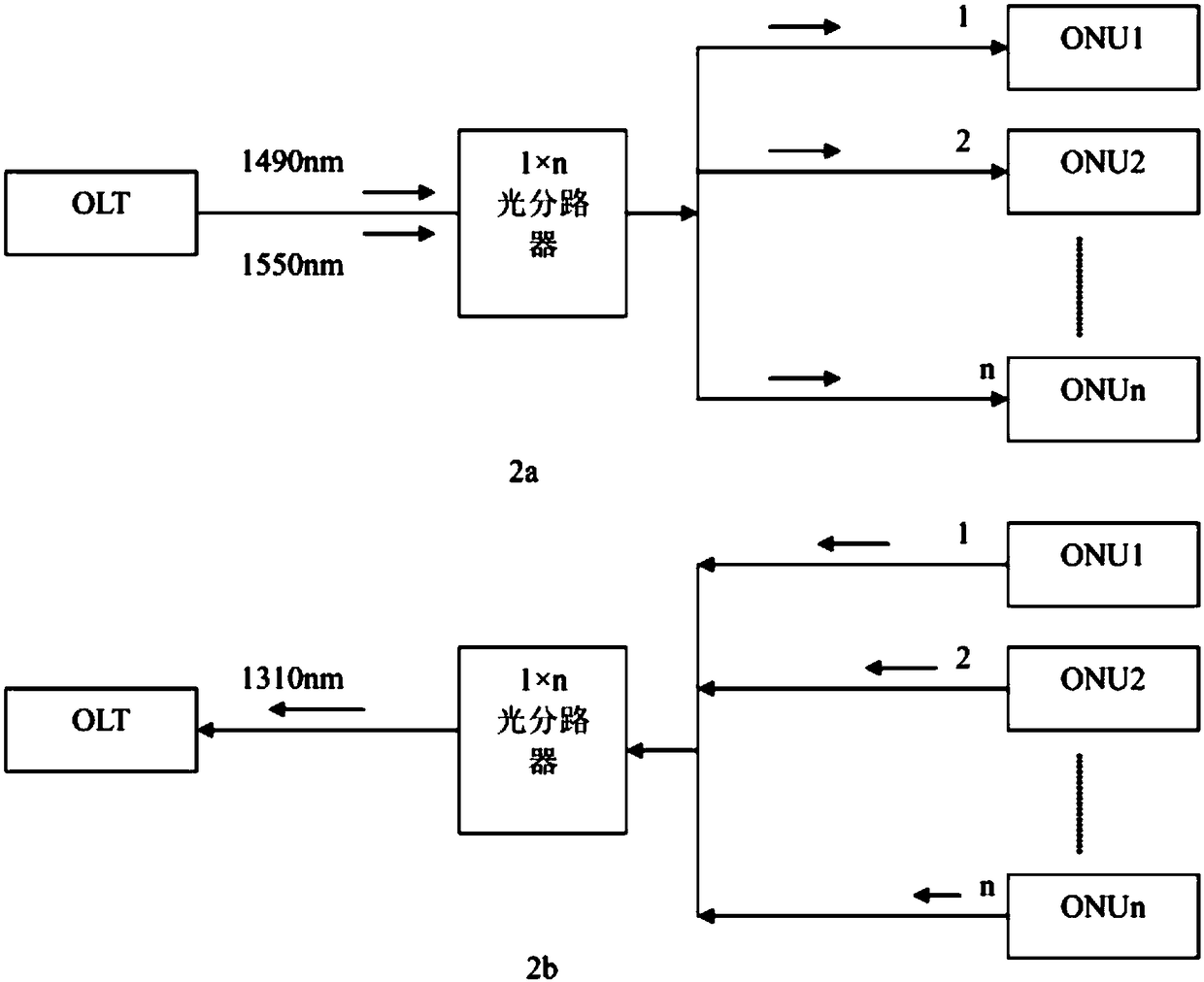
[0070] figure 2 Among them, 2a indicates the collection of downlink light and information flow, and 2b shows the collection of uplink light and information flow, such as figure 2 Taking the downstream light as shown in middle 2a as an example, the PON network optical link loss online accurate measurement method of the present invention includes the following steps:
[0071] The first step is to accurately measure the optical transmit power value of the downlink service of the OLT at a certain moment during the operation of the PON network, that is, to record the accurate input optical power of the OLT optical node, and at the same time, each optical node ONU under the OLT measures the reception of the corresponding downlink service light. power value;
[0072] In the second step, the optical transmit power value of the OLT downlink service and the downlink optical receive power value measured by the ONU of each optical node are collected together through the PON network ser...
Embodiment 2
[0111] Such as figure 2 and Figure 5 As shown, taking the upstream light as an example, the online accurate measurement method for the PON network optical link loss described in this embodiment includes the following steps:
[0112] The first step is to accurately measure the optical transmit power value of the ONU uplink service at a certain moment during the operation of the PON network, that is, to record the accurate optical power of the ONU optical node entering the fiber; at the same time, the OLT measures Corresponding uplink service optical receiving power;
[0113] In the second step, the PON network service brings together the optical transmit power value of the ONU uplink service and the corresponding uplink service optical receive power value measured by the OLT in the time gap of the ONU's uplink service frame at this time;
[0114] The third step is to subtract the optical transmit power value of the ONU uplink service from the corresponding uplink service op...
Embodiment 3
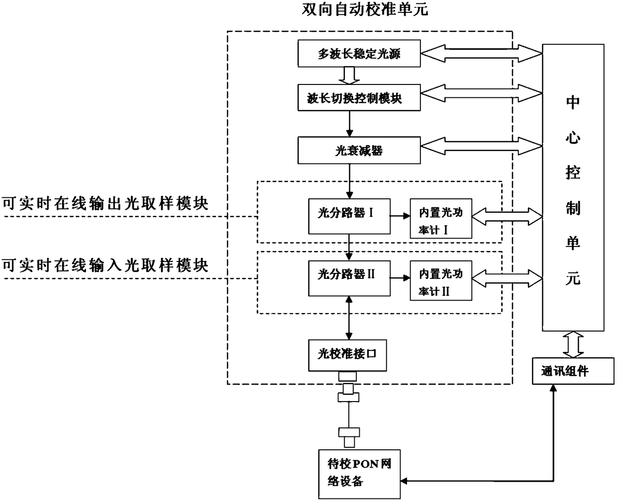
[0120] In this embodiment, the real-time online output optical sampling module and the real-time online input optical sampling module can also share a bidirectional optical splitter, and the output ends of the bidirectional optical splitter are respectively connected to the built-in optical power meter I and the built-in optical power meter II. One input end of the bidirectional optical splitter is connected to the optical calibration interface, and the other input end is connected to the optical adjustment module. The built-in optical power meter I and the built-in optical power meter II are respectively connected to the central control unit. The difference between this scheme and the previous scheme is that it can The online output optical sampling module and the real-time online input optical sampling module share a bidirectional optical splitter.
PUM
 Abstract
Description
Claims
Application Information
 - R&D
- Intellectual Property
- Life Sciences
- Materials
- Tech Scout
- Unparalleled Data Quality
- Higher Quality Content
- 60% Fewer Hallucinations
Browse by: Latest US Patents, China's latest patents, Technical Efficacy Thesaurus, Application Domain, Technology Topic, Popular Technical Reports.
© 2025 PatSnap. All rights reserved.Legal|Privacy policy|Modern Slavery Act Transparency Statement|Sitemap|About US| Contact US: help@patsnap.com


