Precise control method of optical signal power of pon network service
A technology for network services and optical signals, which is applied in data switching networks, selection devices for multiplexing systems, digital transmission systems, etc., and can solve the problems of high cost, high time consumption per unit, and cannot be used as a standard and basis. , to achieve the effect of improving calibration accuracy, improving calibration efficiency, and improving quality management and quality control capabilities
- Summary
- Abstract
- Description
- Claims
- Application Information
AI Technical Summary
Problems solved by technology
Method used
Image
Examples
Embodiment 1
[0087] Under the premise of guaranteeing the transmission quality of optical network data services, the present invention regulates the service transmission optical signal power of the corresponding relevant PON network equipment on the premise of ensuring the receiving optimization power of the relevant PON network equipment; the transmission optimization power is for the actual business of the PON network equipment The basis for the operation evaluation of the transmitted optical signal power.
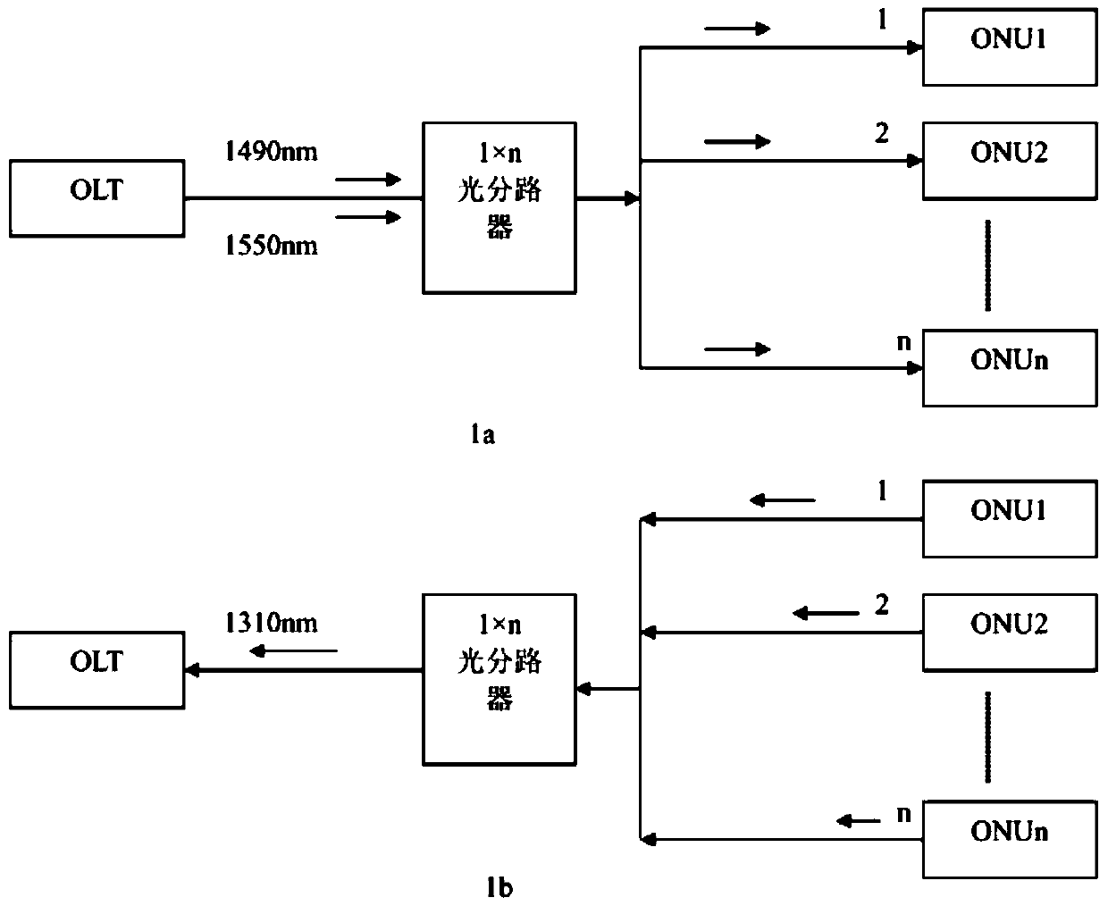
[0088] figure 1 Among them, 1a represents the collection of downlink light and information flow, and 1b shows the collection of uplink light and information flow. figure 1 Taking the downlink light shown in middle 1a as an example, the precise control method of the PON network service optical signal power of the present invention includes the following steps:
[0089] The first step is to accurately measure the optical transmit power value of the downlink service of the OLT at a cer...
Embodiment 2
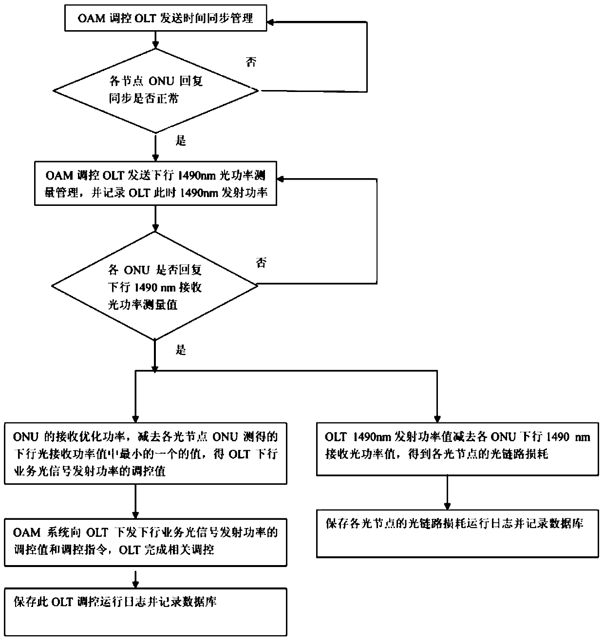
[0133] Such as figure 1 and Figure 4 As shown, taking the upstream light as an example, the precise regulation method of the PON network service optical signal power described in this embodiment includes the following steps:
[0134] The first step is to accurately measure the optical transmit power value of the ONU upstream service at a certain moment during the operation of the PON network, and at the same time, the OLT measures the optical receive power value of the upstream service of the corresponding ONU within the time gap of the ONU upstream service frame;
[0135] In the second step, through the PON network service, the optical transmit power value of the ONU uplink service and the uplink optical receive power value measured by the OLT in each ONU uplink service frame time gap are brought together;
[0136] In the third step, the receiving optimized power of the OLT is subtracted from the uplink optical receiving power value measured by the OLT in the time slot of e...
Embodiment 3
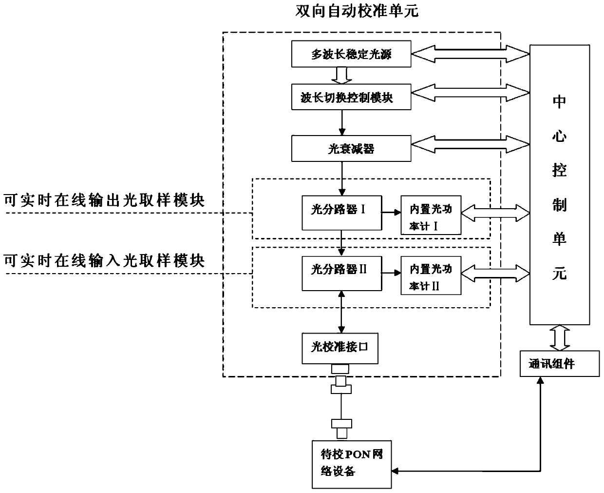
[0146] In this embodiment, the real-time online output optical sampling module and the real-time online input optical sampling module can also share a bidirectional optical splitter, and the output ends of the bidirectional optical splitter are respectively connected to the built-in optical power meter I and the built-in optical power meter II. One input end of the bidirectional optical splitter is connected to the optical calibration interface, and the other input end is connected to the optical adjustment module. The built-in optical power meter I and the built-in optical power meter II are respectively connected to the central control unit. The difference between this scheme and the previous scheme is that it can The online output optical sampling module and the real-time online input optical sampling module share a bidirectional optical splitter.
[0147] Apparently, the present invention is not limited to accurate online measurement and control of PON network service optic...
PUM
 Abstract
Description
Claims
Application Information
 - R&D
- Intellectual Property
- Life Sciences
- Materials
- Tech Scout
- Unparalleled Data Quality
- Higher Quality Content
- 60% Fewer Hallucinations
Browse by: Latest US Patents, China's latest patents, Technical Efficacy Thesaurus, Application Domain, Technology Topic, Popular Technical Reports.
© 2025 PatSnap. All rights reserved.Legal|Privacy policy|Modern Slavery Act Transparency Statement|Sitemap|About US| Contact US: help@patsnap.com


