Automatic Calibration Method for Two-way Transceiver Optical Power of Pon Network Equipment
A technology for automatic calibration and network equipment, applied in electrical components, electromagnetic wave transmission systems, transmission systems, etc., can solve the problems of time-consuming, high labor costs, many influencing factors, and many uncontrollable nodes, etc., to reduce external influences Factors, the effect of improving calibration accuracy and improving calibration efficiency
- Summary
- Abstract
- Description
- Claims
- Application Information
AI Technical Summary
Problems solved by technology
Method used
Image
Examples
Embodiment 1
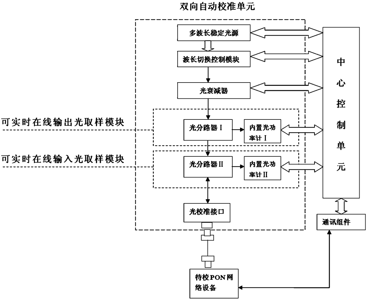
[0077] Such as image 3 As shown, the PON network equipment bidirectional optical power automatic calibration method of the present invention comprises the following steps:
[0078] In the first step, the PON network equipment bidirectional optical power automatic calibration device performs self-calibration;
[0079] In the second step, the external PON network equipment to be calibrated is connected to the PON network equipment bidirectional optical power automatic calibration device, and the optical power of the PON network equipment to be calibrated is calibrated;
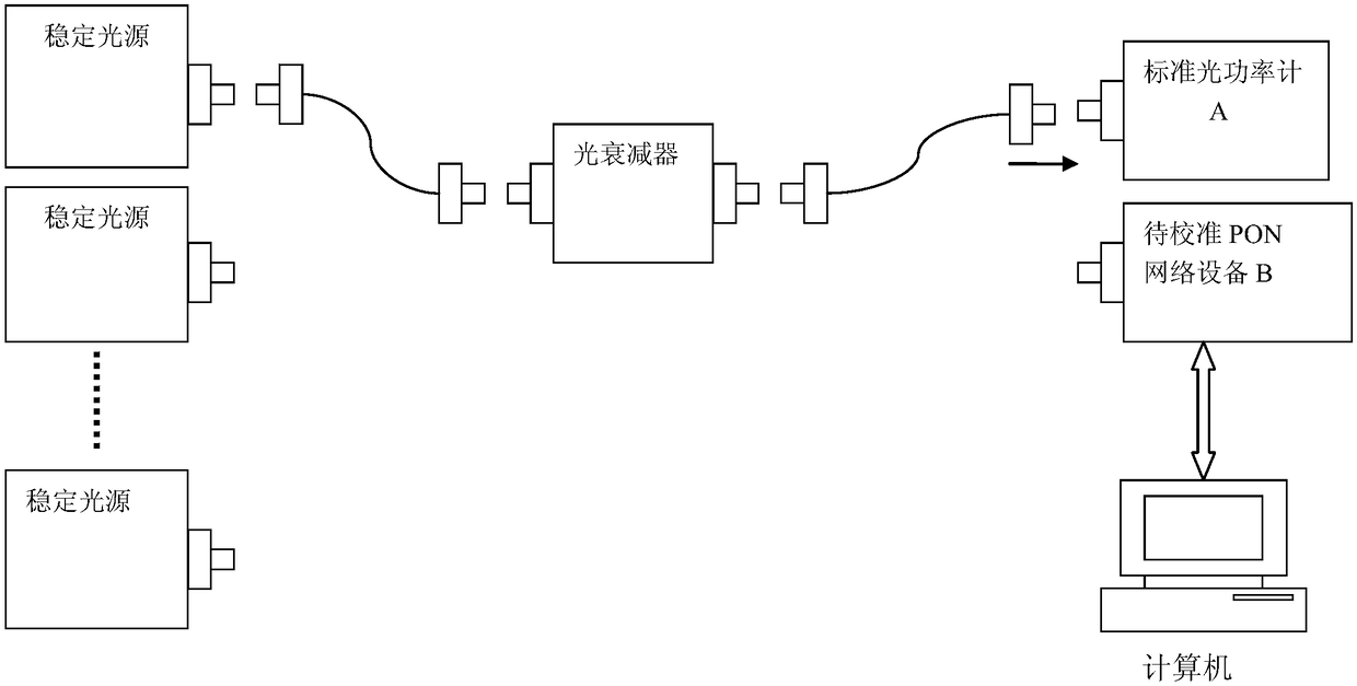
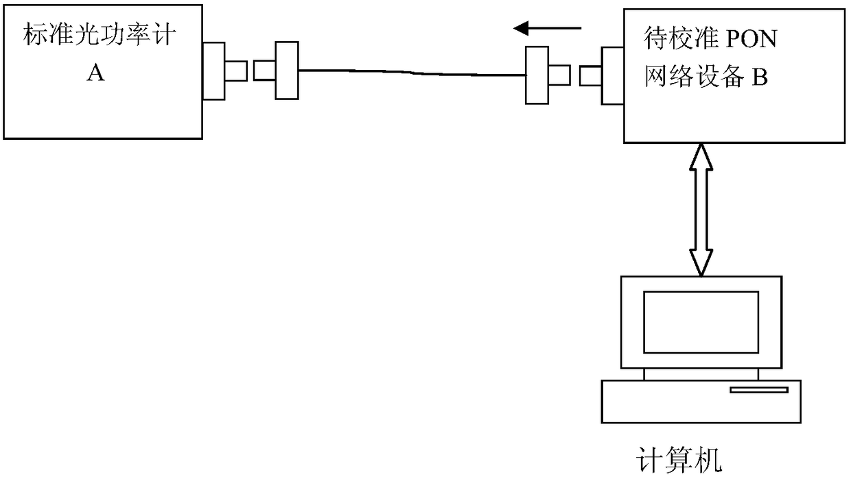
[0080] The above PON network equipment bidirectional optical power automatic calibration device includes at least one set of bidirectional automatic calibration unit and central control unit, the bidirectional automatic calibration unit is connected to the central control unit, and the bidirectional automatic calibration unit includes sequentially connected light adjustment modules, which can The real-time onl...
Embodiment 2
[0105] Such as Figure 12 As shown, in this embodiment, the real-time online output optical sampling module and the real-time online output optical sampling module share a bidirectional optical splitter, and the output ends of the bidirectional optical splitter are respectively connected to the built-in optical power meter I and the built-in optical power meter II. One input end of the bidirectional optical splitter is connected to the optical calibration interface, and the other input end is connected to the optical adjustment module. The built-in optical power meter I and the built-in optical power meter II are respectively connected to the central control unit. Other structures and implementations of this embodiment Example 1 is the same.
Embodiment 3
[0107] Such as Figure 13 As shown, in this embodiment, on the basis of Embodiment 1, the optical splitter II is replaced by an optical path switching device, such as an optical switch. The optical switch is connected to the optical link in a time-sharing manner, and is switched to Built-in optical power meter II.
PUM
 Abstract
Description
Claims
Application Information
 - R&D
- Intellectual Property
- Life Sciences
- Materials
- Tech Scout
- Unparalleled Data Quality
- Higher Quality Content
- 60% Fewer Hallucinations
Browse by: Latest US Patents, China's latest patents, Technical Efficacy Thesaurus, Application Domain, Technology Topic, Popular Technical Reports.
© 2025 PatSnap. All rights reserved.Legal|Privacy policy|Modern Slavery Act Transparency Statement|Sitemap|About US| Contact US: help@patsnap.com


