Method for accurately regulating and controlling business optical signal power of PON network

A network service and optical signal technology, applied in the direction of data exchange network, multiplexing system selection device, electromagnetic wave transmission system, etc., can solve the problems that cannot be used as a standard and basis, high cost, and time-consuming for a single unit , to achieve the effect of improving quality management and quality control capabilities, improving calibration accuracy, and improving calibration efficiency

Active Publication Date: 2016-07-20
SHANDONG SENTER ELECTRONICS
View PDF5 Cites 5 Cited by
  • Summary
  • Abstract
  • Description
  • Claims
  • Application Information

AI Technical Summary

Problems solved by technology

[0013] At present, OAM can monitor the optical transmission and reception optical power of optical network operating equipment online. However, the number of PON network equipment (OLT, ONU) is huge, and precise calibration is time-consuming and costly for these equipment. Currently, these optical Network equipment can only be roughly calibrated, and the error is about ±3dB
This makes the emission and reception optical power of optical equipment monitored by OAM only as a reference for regulating the optical signal power of PON network services, and cannot be used as a standard and basis

Method used


Image

  • Method for accurately regulating and controlling business optical signal power of PON network
  • Method for accurately regulating and controlling business optical signal power of PON network
  • Method for accurately regulating and controlling business optical signal power of PON network

Examples


Embodiment 1

[0087] Under the premise of guaranteeing the transmission quality of optical network data services, the present invention regulates the service transmission optical signal power of the corresponding relevant PON network equipment on the premise of ensuring the receiving optimization power of the relevant PON network equipment; the transmission optimization power is for the actual business of the PON network equipment The basis for the operation evaluation of the transmitted optical signal power.

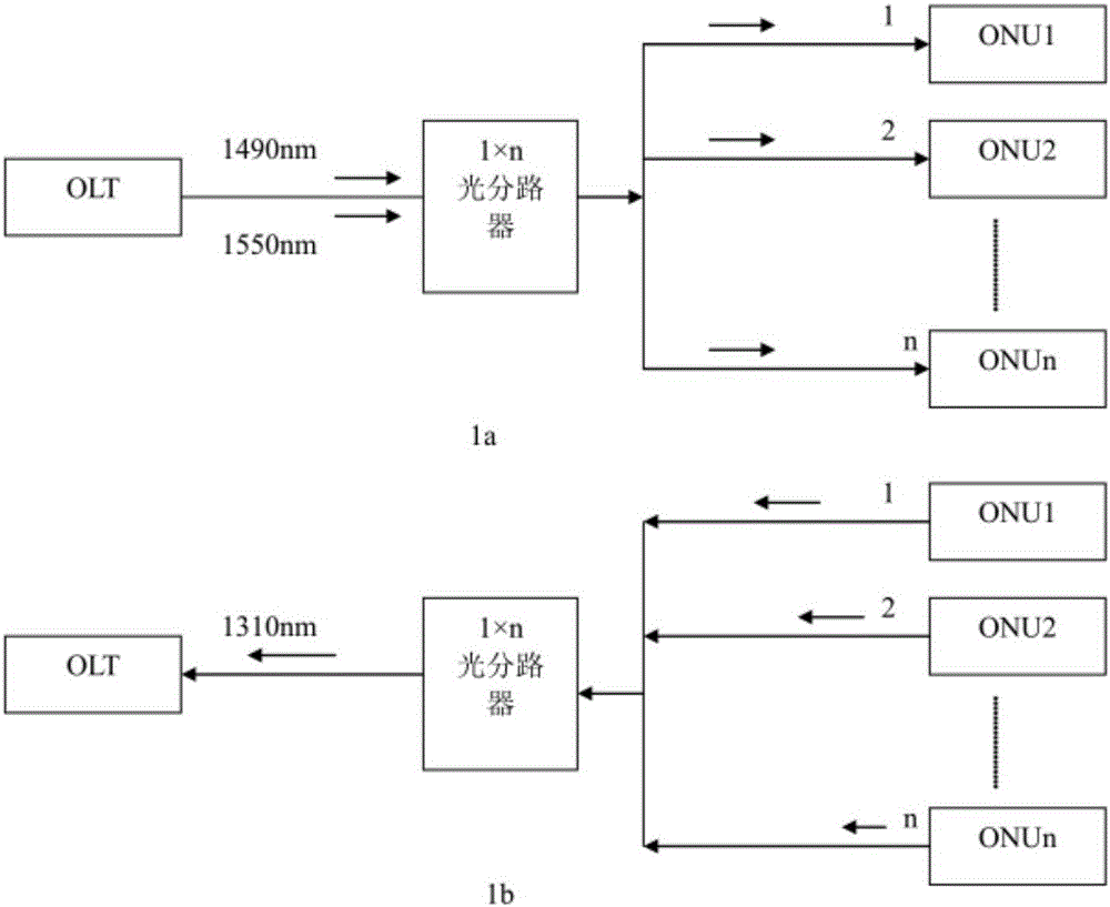
[0088] figure 1 Among them, 1a represents the collection of downlink light and information flow, and 1b shows the collection of uplink light and information flow. figure 1 Taking the downlink light shown in middle 1a as an example, the precise control method of the PON network service optical signal power of the present invention includes the following steps:

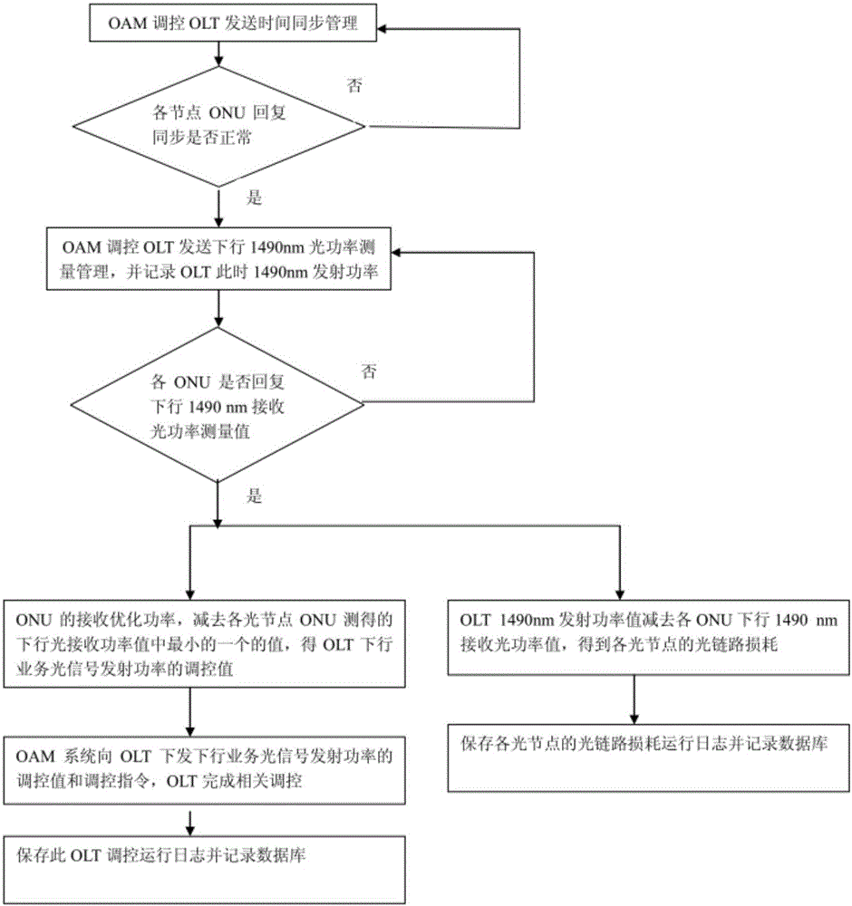
[0089] The first step is to accurately measure the optical transmit power value of the downlink service of the OLT at a cer...

Embodiment 2

[0133] Such as figure 1 and Figure 4 As shown, taking the upstream light as an example, the precise regulation method of the PON network service optical signal power described in this embodiment includes the following steps:

[0134] The first step is to accurately measure the optical transmit power value of the ONU upstream service at a certain moment during the operation of the PON network, and at the same time, the OLT measures the optical receive power value of the upstream service of the corresponding ONU within the time gap of the ONU upstream service frame;

[0135] In the second step, through the PON network service, the optical transmit power value of the ONU uplink service and the uplink optical receive power value measured by the OLT in each ONU uplink service frame time gap are brought together;

[0136] In the third step, the receiving optimized power of the OLT is subtracted from the uplink optical receiving power value measured by the OLT in the time slot of e...

Embodiment 3

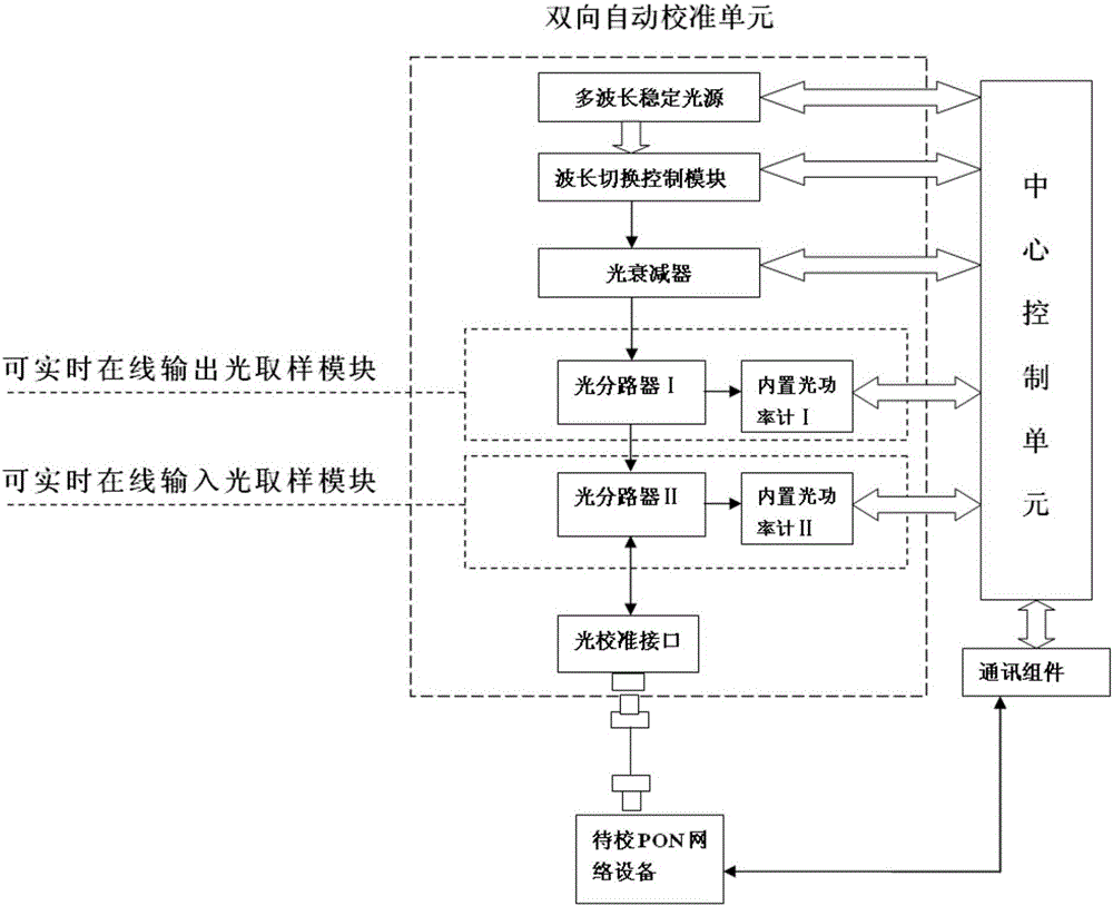
[0146] In this embodiment, the real-time online output optical sampling module and the real-time online input optical sampling module can also share a bidirectional optical splitter, and the output ends of the bidirectional optical splitter are respectively connected to the built-in optical power meter I and the built-in optical power meter II, One input end of the bidirectional optical splitter is connected to the optical calibration interface, and the other input end is connected to the optical adjustment module. The built-in optical power meter I and the built-in optical power meter II are respectively connected to the central control unit. The difference between this scheme and the previous scheme is that it can The online output optical sampling module and the real-time online input optical sampling module share a bidirectional optical splitter.

[0147] Apparently, the present invention is not limited to accurate online measurement of PON network service optical signal po...


PUM


Abstract

The invention belongs to the field of operation quality assessment and monitor configuration of PON optical network and specifically relates to a method for accurately regulating and controlling business optical signal power of a PON network. During an operation process of the optical network, an optical network device accurately calculates transmit-receive light power values of related business wavelength of each optical node in optical network topology for a certain moment, the transmit-receive light power values of related business wavelength of each optical node at the very moment are gathered through optical network business, the received optimal power of the related business wavelength of any optical node is subtracted by the measured receive light power value of the related business wavelength at the moment, the obtained difference is a regulation and control value of the emission power of related business wavelength of the optical node optical network equipment corresponding to the optical node in the optical network topology, and related equipment is accurately regulated and controlled. The method realizes on-line accurate regulation and control of various business optical signal power of an optical network, ensures optimal work state of the network, and greatly improves the operation and management quality of the optical network.

Description

technical field [0001] The invention belongs to the field of PON optical network operation quality evaluation and monitoring configuration, and in particular relates to a method for precise regulation and control of PON network service optical signal power. Background technique [0002] PON (Passive Optical Network) access network technology is recognized in the industry as the best solution for FTTx, and it is also the main access method of fiber-to-the-home. The scale of the optical network and the number of terminals are huge. This technology can enable multiple users to share a single Root optical fiber, so that no active components are used in the optical distribution network (ODN), that is, no "optical / electrical / optical" conversion is required. This point-to-multipoint architecture greatly reduces network installation, management and maintenance. cost. [0003] In the PON system (GPON, EPON, etc.), the uplink signal uses a wavelength of 1310nm, and the downlink signa...

Claims


Application Information

Patent Timeline
Patent Type & Authority Applications(China)
IPC IPC(8): H04Q11/00H04L12/24H04B10/079
CPCH04B10/07955H04L41/00H04Q11/0067
Inventor 张海峰蔡富东李全用刘在平张晓宇王景吕昌峰崔利
Owner SHANDONG SENTER ELECTRONICS
Why Eureka
Try Eureka