a paper cutter

A paper cutter and paper cutting technology, which is applied in metal processing and other directions, can solve the problems of affecting paper cutting work, paper jams, and paper cutting machines cannot complete the paper pushing work, etc., so as to improve production speed and ensure paper cutting accuracy. Effect

Active Publication Date: 2018-04-10
ZHEJIANG HUAYUE PACKING MACHINERY
View PDF7 Cites 8 Cited by
  • Summary
  • Abstract
  • Description
  • Claims
  • Application Information

AI Technical Summary

Problems solved by technology

The paper cutter of the prior art comprises a paper cutting platform and a paper pushing frame which is movable back and forth on the platform surface of the second half of the paper cutting platform. There is a grid tooth, because there is a gap between the bottom surface of the paper pushing block and the platform surface of the paper cutting platform, so it is easy for the paper to enter the bottom of the paper pushing block during the paper pushing process, that is, the paper jam phenomenon, which will cause the paper cutter to fail to complete the normal operation. The paper pushing work will affect the paper cutting work; in addition, in order to increase the paper cutting speed, it is necessary to have a faster paper pushing speed, but if the paper pushing speed is fast, it is easy to appear that the paper pushing block has stopped pushing the paper, and the paper It is also necessary to move forward with inertia, so that the paper cutting accuracy cannot be guaranteed, so it cannot meet the needs of high-speed paper cutting, and the production speed of the paper cutter is difficult to be further improved.

Method used


Image

  • a paper cutter
  • a paper cutter
  • a paper cutter

Examples


Embodiment Construction

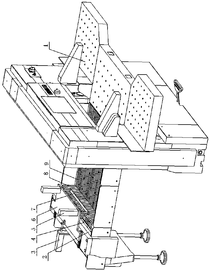
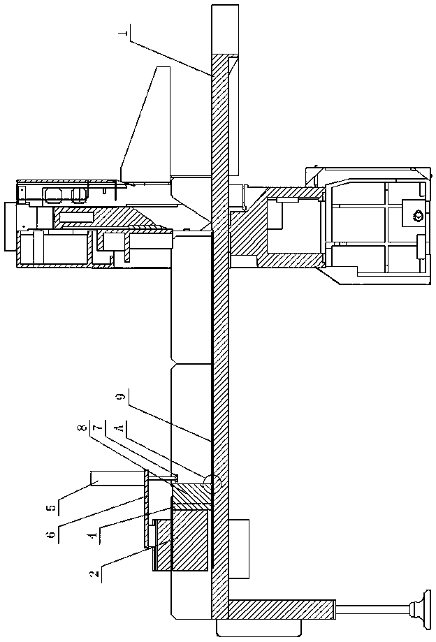
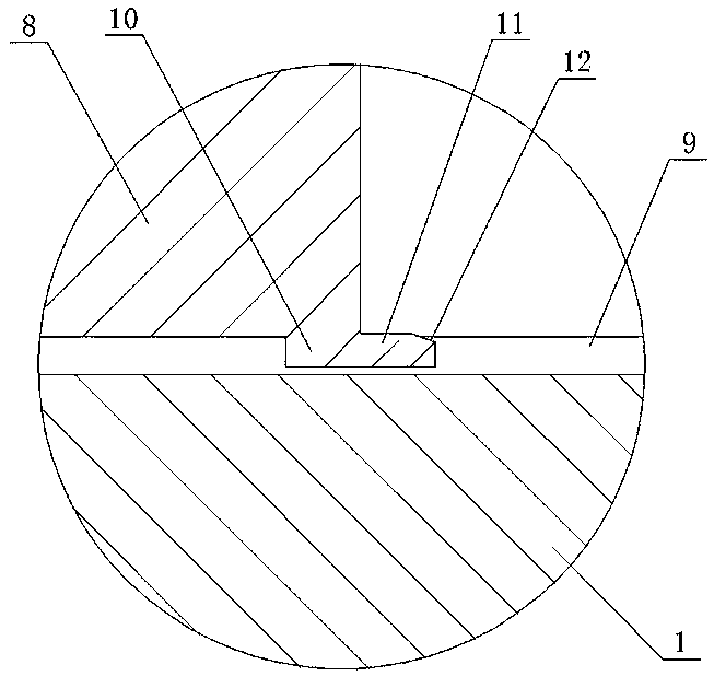
[0013] As shown in the figure, a paper cutting machine of the present invention includes a paper cutting platform 1 and a paper pushing frame 2 movably arranged on the surface of the rear half of the paper cutting platform. The front end of the paper pushing frame 2 is fixedly installed with paper pushing Block 4, the paper-pushing surface of the paper-pushing block 4 is provided with grid teeth 8, and the surface of the rear half of the paper cutting platform is horizontally arranged with a plurality of narrow strip-shaped shallow grooves 9 in the front and rear direction, and the narrow strip-shaped shallow grooves 9 and the grid Corresponding to the teeth 8, the bottom of the grid teeth 8 has a downwardly extending insert plate 10 inserted into the narrow strip-shaped shallow groove 9, the insert plate 10 has a front extension 11, and the top surface of the front extension 11 is high On the platform surface of the paper cutting platform 1, the top surface of the front extensi...


PUM


Abstract

The invention discloses a paper cutting machine which comprises a paper cutting platform and a paper pushing frame. The paper pushing frame is moved front and back on the surface of the rear half part of the paper cutting platform. A paper pushing block is fixedly installed at the front end of the paper pushing frame. The paper pushing face of the paper pushing block is provided with gate teeth. The paper cutting machine is characterized in that the surface of the rear half part of the paper cutting platform is transversely provided with multiple narrow-strip-shaped shallow slots in the front-back direction, the narrow-strip-shaped slots correspond to the gate teeth, the bottoms of the gate teeth are provided with inserting plates extending downwards, and the inserting plates are inserted into the narrow-strip-shaped shallow slots; and a movable plate is arranged on the top of the paper pushing frame., the movable plate is pushed by a longitudinal air cylinder to move in the front-back direction, a paper pressing plate is arranged in front of the paper pushing block, the paper pressing plate is pushed by a vertical air cylinder to move in the vertical direction, and the vertical air cylinder is fixedly installed at the front end of the movable plate. According to the paper cutting machine, the technical problems of paper clamping and inertia forward movement of paper piles in the paper pushing process can be solved, paper cutting precision is ensured, the high-speed paper cutting requirement for the paper cutting machine can be better met, and the production speed of the paper cutting machine is increased.

Description

Technical field [0001] The invention relates to the technical field of printing and packaging machinery, in particular to a paper cutter. Background technique [0002] The paper cutter is a device that cuts large-size paper into smaller-size paper of the required size. A paper cutter in the prior art includes a paper cutting platform and a paper pushing frame movably arranged on the surface of the rear half of the paper cutting platform. The front end of the paper pushing frame is fixedly installed with a paper pushing block, and the paper pushing surface of the paper pushing block It is equipped with grid teeth. Because there is a gap between the bottom surface of the paper pushing block and the platform surface of the paper cutting platform, it is easy to cause paper to enter the bottom of the paper pushing block during the paper pushing process, which is the paper jam, which causes the paper cutter to fail to complete normally In addition, in order to increase the cutting spe...

Claims


Application Information

Patent Timeline
Patent Type & Authority Patents(China)
IPC IPC(8): B26D7/02B26D7/06
CPCB26D7/025B26D7/0608
Inventor 王建彪黄仁从高泉全
Owner ZHEJIANG HUAYUE PACKING MACHINERY
Why Eureka
Try Eureka