
Plastic particle mixing device

A mixing device and plastic granule technology, applied in the field of plastic machinery, can solve problems such as heavy workload, enterprise loss, and affecting the quality of plastic products, and achieve the effect of improving efficiency and improving uniformity

Inactive Publication Date: 2016-09-28
重庆敏驰塑胶有限公司
View PDF1 Cites 4 Cited by
  • Summary
  • Abstract
  • Description
  • Claims
  • Application Information

AI Technical Summary

Problems solved by technology

[0002] In the plastic product industry, it is often necessary to mix a variety of plastic particles according to the process requirements of the product. For large and medium-sized manufacturers, due to the large number of plastic particles that need to be mixed every day, the traditional mixing method is often The plastic particles are mixed manually, and the manual mixing can only achieve partial mixing, uneven mixing and poor mixing effect, so the produced products are prone to color difference, which seriously affects the quality of the final plastic products , which caused huge losses to the enterprise. In addition, manual stirring and mixing of raw materials is used, which has a large workload and low work efficiency, which greatly increases the labor intensity of operators and increases the burden on operators, which can no longer meet the needs of enterprise production.
[0003] In order to solve the above problems, the Chinese Patent Publication No. CN204505592U discloses a plastic particle mixing and stirring device; the device includes a frame, a motor, and a rotating shaft seat fixed at the bottom of the frame. The inner cylinder is set on the frame and at the same center as the rotating shaft seat, and the inside of the inner cylinder is also provided with a screw propulsion rod, which is fixedly connected to the rotating shaft seat; the inner cylinder is also provided with an outer cylinder, The bottom of the inner cylinder is also fixedly provided with a feed hopper connected with the inside of the inner cylinder, and the inner cylinder is also provided with a circulation port connected with the outer cylinder, and the bottom of the outer cylinder is also provided with a discharge hopper. mouth; although the device can push the plastic particles continuously and circularly through the screw push rod, the mixing effect of the screw propulsion on the plastic particles is not good, and the plastic particles between the inner cylinder and the outer cylinder are in an idle state, making the The mixing efficiency of plastic particles has not been improved, so it needs to be improved in order to improve the uniformity of mixed plastic particles through this device

Method used


Image

  • Plastic particle mixing device

Examples


Embodiment Construction

[0016] The present invention will be described in further detail below by means of specific embodiments:

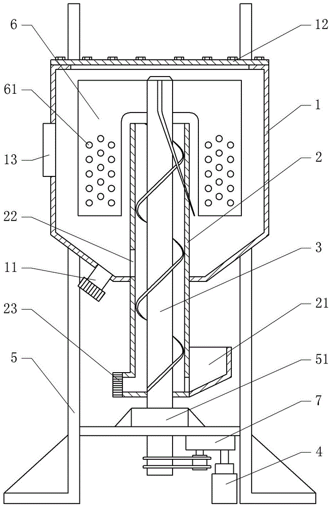
[0017] The reference signs in the drawings of the specification include: outer cylinder 1, inner cylinder 2, screw push rod 3, motor 4, frame 5, stirring paddle 6, reducer 7, discharge valve 11, cover 12, Visible window 13, feed hopper 21, circulating feed port 22, discharge valve 2 23, rotating shaft seat 51, filter material hole 61.

[0018] The embodiment is basically as figure 1 As shown: the plastic particle mixing device includes a frame 5, a motor 4, an inner cylinder 2, an outer cylinder 1 and a screw rod 3; the outer cylinder 1 is fixed on the frame 5, and the inner cylinder 2 is fixed on the outer cylinder 1 Inside, and the upper end of the inner cylinder 2 is open, the lower end of the inner cylinder 2 protrudes from the bottom of the outer cylinder 1, the screw push rod 3 is arranged in the inner cylinder 2; the bottom of the frame 5 is fixed with a rotating ...


PUM

PropertyMeasurementUnit
Slopeaaaaaaaaaa

Abstract

This patent discloses a plastic particle mixing device, which relates to the technical field of plastic machinery; the plastic particle mixing device includes a frame, a motor, an inner cylinder, an outer cylinder and a screw push rod; the outer cylinder is fixed on the frame, and the inner cylinder The body is fixed in the outer cylinder, and the upper end of the inner cylinder is open, the screw push rod is set in the inner cylinder, and the motor can drive the screw push rod to rotate in the inner cylinder; Hopper, the middle part of the inner cylinder is provided with a circulation port connecting the inner cylinder and the outer cylinder, and the bottom of the outer cylinder is provided with a discharge port; the upper end of the screw push rod is fixedly connected with a stirring paddle; when the device is working, the screw The push rod can make the material circulate between the inner cylinder and the outer cylinder, and the stirring paddle can stir the material between the inner cylinder and the outer cylinder, so the device can circulate the material, and the efficiency is also improved. improve.

Description

technical field [0001] The invention relates to the technical field of plastic machinery, in particular to a plastic particle mixing device. Background technique [0002] In the plastic product industry, it is often necessary to mix a variety of plastic particles according to the process requirements of the product. For large and medium-sized manufacturers, due to the large number of plastic particles that need to be mixed every day, the traditional mixing method is often The plastic particles are mixed manually, and the manual mixing can only achieve partial mixing, uneven mixing and poor mixing effect, so the produced products are prone to color difference, which seriously affects the quality of the final plastic products , which caused huge losses to the enterprise. In addition, manual stirring and mixing of raw materials is used, which has a large workload and low work efficiency, which greatly increases the labor intensity of operators and increases the burden on operat...

Claims


Application Information

Patent Timeline
IPC IPC(8): B29B7/16
CPCB29B7/16
Inventor 杨治焱
Owner 重庆敏驰塑胶有限公司
Learn More