
Continuous material conveying device

A technology for conveying devices and materials, applied in the direction of conveyor control devices, conveyors, conveyor objects, etc., can solve the problems of incapable material conveying, complex mechanism, low efficiency, etc., and achieve the effect of continuous conveying

Inactive Publication Date: 2016-09-28
吴洋
View PDF8 Cites 3 Cited by
  • Summary
  • Abstract
  • Description
  • Claims
  • Application Information

AI Technical Summary

Problems solved by technology

However, the above-mentioned conveying mechanism is relatively complicated, and cannot realize continuous conveying of materials, and the efficiency is low

Method used


Image

  • Continuous material conveying device
  • Continuous material conveying device

Examples


Embodiment Construction

[0013] The present invention will be further described in detail below in conjunction with the accompanying drawings and embodiments.

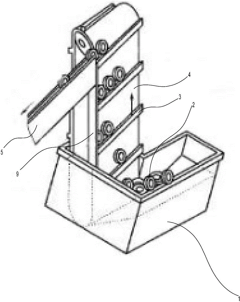
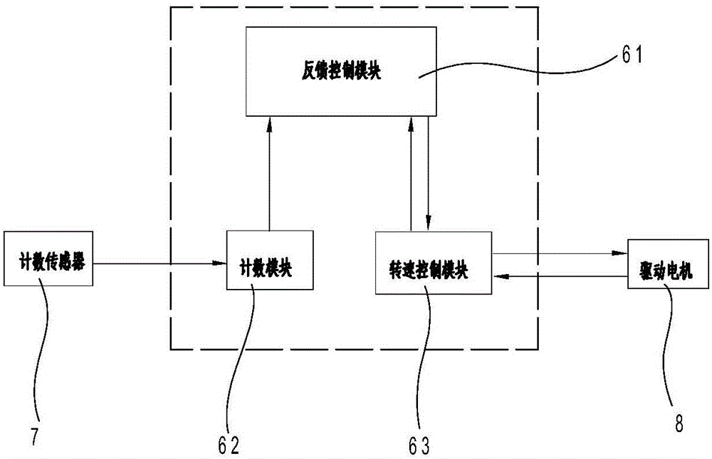
[0014] Such as figure 1 , 2 As shown, the continuous conveying device for materials in this implementation includes a material box 1 for holding materials 2, a conveying belt 4, a conveying plate 3, a conveying track 5, a baffle 9, a conveying roller, a drive motor 8, and a counting sensor 7 and the controller.

[0015] Wherein, the conveyor belt 4 is erected in the material box 1, one end of the conveyor belt 4 is placed in the material box 1, the other end of the conveyor belt 4 is located above the material box 1, and a plurality of conveyor plates are arranged at intervals in an oblique direction on the conveyor belt 4 3. A conveyor track 5 is arranged above the conveyor belt 4. The conveyor track 5 is arranged obliquely. The inclination angle of the conveyor track 5 is greater than or equal to the inclination angle of the conveyor plate...


PUM


Abstract

The invention discloses a continuous material conveying device. The device comprises a material box for storing materials. The device is characterized in that a conveyor belt is vertically arranged in the material box, wherein one end of the conveyor belt is positioned in the material box while the other end of the conveyor belt is positioned above the material box; a plurality of conveying plates are obliquely arranged at intervals on the conveyor belt; a conveying rail is obliquely arranged above the conveyor belt, and the obliquing angle of the conveying rail is not less than the obliquing angles of the conveying plates; one side of the conveying rail is close to the side edge of the conveyor belt; a baffle plate, which is arranged below the conveying rail, is positioned at the side edge of the conveyor belt and used for preventing the materials from falling off from the conveying plates.

Description

technical field [0001] The invention relates to a conveying device, in particular to a continuous conveying device for materials. Background technique [0002] In the field of mechanical production and processing, it is often necessary to transport materials to realize automated production. For example, the Chinese invention patent "A Conveying Mechanism" with publication number CN 104340677A includes a vibrating feeding device; A pause device at the output end; the transport hopper is arranged obliquely along its transport direction, and the output end is the lower end of the transport hopper in the transport direction. In the conveying mechanism provided by the invention, the material is transported into the transport hopper, and during the vibrating process of the vibrator, the material moves to the output end of the transport hopper; after the first material passes through the output end, the suspension device suspends the second material, After the processing of the f...

Claims


Application Information

Patent Timeline
Patent Type & Authority Applications(China)
IPC IPC(8): B65G47/12B65G17/12B65G43/08B65G47/44
CPCB65G47/12B65G17/12B65G43/08B65G47/44B65G2203/0241
Inventor 吴洋
Owner 吴洋
Learn More