Screening fluffer

A technology of deflagging machine and deflagging area, which is applied in the direction of textile and papermaking, fiber raw material processing, raw material separation, etc. It can solve the problems that cannot be deflagged, achieve the effect of reducing the number of equipment, improving work efficiency, and avoiding waste

Inactive Publication Date: 2016-09-28
李昊
View PDF9 Cites 1 Cited by
  • Summary
  • Abstract
  • Description
  • Claims
  • Application Information

AI Technical Summary

Problems solved by technology

[0004] The invention proposes a screening and deflaking machine, which solves the problem that the pulp screening machine in the prior art can only screen the pulp but cannot decompose it

Method used


Image

  • Screening fluffer
  • Screening fluffer
  • Screening fluffer

Examples


Embodiment 1

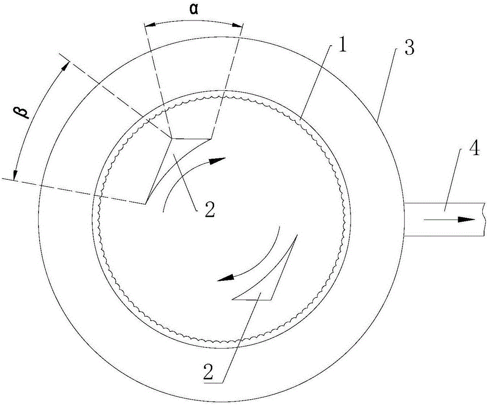
[0023] Such as figure 2 As shown, this embodiment is based on the prior art, and a circular arc transition section is set between the positive pressure section and the negative pressure section of the rotor 2, and the arc transition section is concentric with the screen drum 1 In this way, a debonding zone γ is formed between the arc transition section and the screen drum 1, and the paper sheets or fiber bundles will receive bite, friction, and agitation from the arc transition section and the screen drum in the decompression zone γ until they are dispersed In order to be able to pass through the holes / slots on the surface of the screen drum 1 and enter the fibers of the good stock, the finally formed good stock is discharged from the good stock outlet 4 .

[0024] In addition, by adding a circular arc transition section, a buffer zone can be formed between the positive pressure zone α and the negative pressure zone β. If there is no such buffer zone, the pulp will change fro...

Embodiment 2

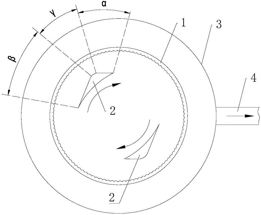
[0026] Such as image 3 As shown, it is another embodiment of the patent of the present invention, which is the same as figure 2 The difference is that the rotor 2 in this embodiment is located outside the screen drum 1. At this time, the pulp passes into the area between the screen drum 1 and the shell 3. Under the action of the positive pressure area α, the good pulp is discharged into the screen The inner cavity of the drum 1, while the paper sheets or fiber bundles are still deflated in the deflation zone γ area between the screen drum 1 and the circular arc transition section of the rotor 2.

Embodiment 3

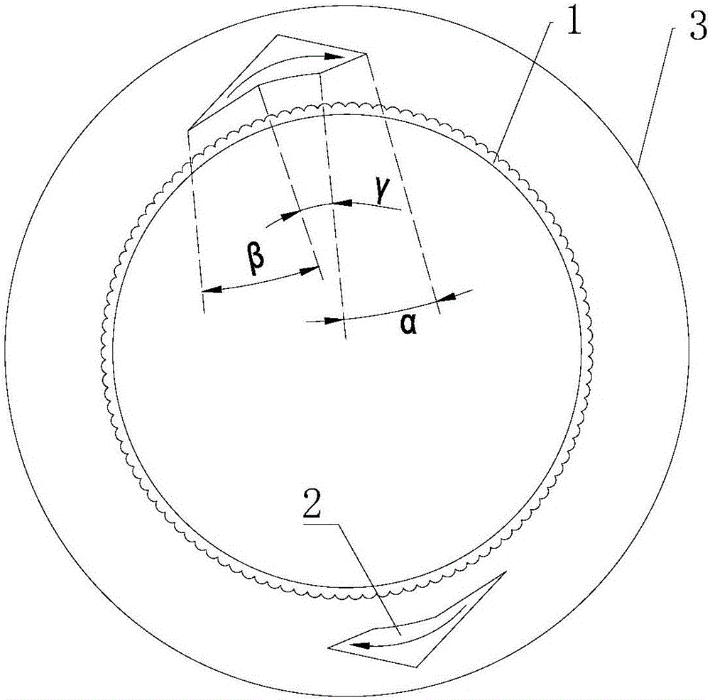
[0028] Such as Figure 4 As shown, it is another embodiment of the patent of the present invention. This embodiment combines the characteristics of Embodiment 1 and Embodiment 2. It includes two concentric screen drums 1, and the rotor 2 is arranged between the two screen drums 1. In between, the pulp passes into the area between the two screen drums 1.

[0029] Such as Figure 5 Shown is a schematic structural view of the rotor 2 in this embodiment, wherein the inner positive pressure section 21, negative pressure section 22 and circular arc transition section 23 serve the inner screen drum 1, and the good pulp formed by it is discharged into The inner cavity of the inner screen drum 1; the outer positive pressure section 21, negative pressure section 22 and arc transition section 23 serve the outer screen drum 1, and the good pulp formed by it is discharged into the outer screen drum 1, of course , There is also a shell on the outside of the external screen drum 1 . The r...


PUM


Abstract

The invention provides a screening fluffer. The screening fluffer is used for solving the problem that a paper pulp screening machine in the prior art can only screen paper pulp and is incapable of fluffing the paper pulp. The screening fluffer comprises a screen cylinder and a rotor wing arranged in the screen cylinder, the screen cylinder and the rotor wing rotate oppositely, the rotor wing comprises a positive pressure section and a negative pressure section, an arc transition section is arranged between the positive pressure section and the negative pressure section of the rotor wing and is concentric with the screen cylinder, and a fluffing region is formed between the arc transition section and the screen cylinder. The screening fluffer is simple in structure, convenient to use, multipurpose and high in practicability, and it is not needed to additionally arrange an individual fluffer.

Description

technical field [0001] The invention relates to the technical field of papermaking machinery and equipment, in particular to a screening and deflaking machine integrating screening and deflaking. Background technique [0002] Pulp screening machine is one of the important equipment commonly used in papermaking machinery. It mainly completes the work of extracting good pulp from pulp, such as figure 1 As shown, it is a schematic structural diagram of a pulp screening machine in the prior art. Its basic working principle is: pulp is continuously fed into the inner cavity of the corrugated screen drum 1, and a plurality of rotors 2 uniformly distributed on the inner circumference of the screen drum 1 are rotating. Among them, the formed positive pressure zone α pushes the pulp in the screen drum 1 into the shell 3 through the holes / slits on the screen drum 1 to form the accept pulp, and then discharge it from the accept pulp outlet 4. [0003] Since the pulp passing into the s...

Claims


Application Information

Patent Timeline
Patent Type & Authority Applications(China)
IPC IPC(8): D21D5/06D21B1/34
CPCD21D5/06D21B1/345
Inventor 李昊
Owner 李昊
Why Eureka
Try Eureka