Sheet inspection device

A technology for inspecting devices and sheets, which is applied in the direction of optical testing for flaws/defects, etc., can solve the problems of large-scale devices, increased costs, low detection accuracy, etc., and achieve the effect of miniaturization and simple structure

Active Publication Date: 2016-09-28
ORMON CORP
View PDF7 Cites 14 Cited by
  • Summary
  • Abstract
  • Description
  • Claims
  • Application Information

AI Technical Summary

Problems solved by technology

[0006] However, conventional methods have a problem in that although abnormalities on the front side of the sheet and inside the sheet can be detected with high precision, the detection accuracy of abnormalities on the back side of the sheet (the surface op...

Method used


Image

  • Sheet inspection device
  • Sheet inspection device
  • Sheet inspection device

Examples


no. 1 example

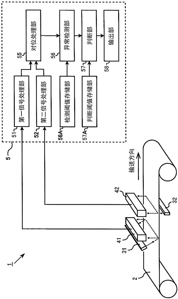
[0072] figure 1 It is a block diagram of the sheet inspection device 1 of this embodiment. The sheet inspection device 1 is a system used to automatically detect abnormalities and defects of sheet articles in a production line that manufactures and processes sheet articles.

[0073] The sheet inspection apparatus 1 includes, as an illumination system: a first light source 31 for irradiating visible light to the front (first surface) of a sheet-shaped inspection object 2; ) irradiates visible light. In addition, the sheet inspection apparatus 1 has, as a measurement system, a first imaging sensor 41 and a second imaging sensor 42 arranged on the front side of the inspection object 2 . The first imaging sensor 41 is a reflected light measurement system, and is configured to capture light irradiated from the first light source 31 and diffusely reflected by the object 2. The second imaging sensor 42 is a transmitted light measurement system, and is configured to capture light fr...

no. 2 example

[0106] Next, a sheet inspection device related to the second embodiment will be described. The second embodiment is characterized in that by adding a reflected light measurement system using infrared light to the structure of the first embodiment, it is possible to discriminate whether the front foreign matter is metal or non-metal.

[0107] Figure 7 It is a block diagram of the sheet inspection apparatus 1 of the second embodiment. In addition to the structure of the first embodiment (refer to figure 1 ), a third light source 33 that irradiates infrared light to the front (first surface) of the object 2 to be inspected, and a third imaging sensor 43 disposed on the front (first surface) of the object 2 to be inspected. The third imaging sensor 43 is an image sensor sensitive to the wavelength of infrared light, and is configured to capture infrared light irradiated from the third light source 33 and diffusely reflected by the inspection object 2 .

[0108] The sheet inspe...

no. 3 example

[0118] Figure 10A The configurations of the lighting system and the measurement system of the sheet inspection apparatus 1 of the third embodiment are shown. In the third embodiment, the reflected visible light of the first light source 31 , the transmitted visible light of the second light source 32 , and the reflected infrared light of the third light source 33 are captured by one imaging device 4 . As a shooting device 4, such as Figure 10B As shown, the three line sensors of the first imaging sensor 41 , the second imaging sensor 42 , and the third imaging sensor 43 use 3-line cameras arranged staggered in the conveying direction.

[0119] In this structure, when the imaging device 4 is arranged on the front side (first surface side) of the object 2 to be inspected, the first light source 31 and the third light source 33 are arranged on the same front side as the imaging device 4, and the second light source 31 is arranged on the same front side as the imaging device 4....


PUM


Abstract

The invention relates to a sheet inspection device, and provides a technology which can detect abnormity of the front surface side of a sheet inspected object in high precision and abnormity of a back surface side by a simple structure. A first image of light reflected by the inspected object and a second image of light passing through the inspected object are shot and used to detect abnormal positions on the inspected object. In the abnormal positions, under the condition that a pixel value of the first image and a pixel value of the second image are reduced than a normal value when the inspected object has no abnormity, a processing portion determines the abnormity on the abnormal position is foreign body adhesion or a first surface foreign body mixed in the first surface side of the inspected object, or foreign body adhesion or a second surface foreign body mixed in the second surface side on the opposite side of the first surface, based on reduction degree of the pixel value of the first image relative to the normal value and the reduction degree of the pixel value of the second image relative to the normal value.

Description

technical field [0001] The present invention relates to a technique for detecting an abnormal part of a sheet-like object to be inspected. Background technique [0002] An inspection device is used on a production line for the manufacture or processing of sheet-like items. This device uses visible light and infrared light to irradiate the sheet and then uses a camera to capture images of the transmitted light or reflected light to detect defects on the sheet. Abnormal parts (foreign matter, dirt, scars, etc.). [0003] In such an inspection device, it is relatively easy to detect an abnormality on a sheet, but it is very difficult to determine in detail and accurately what kind of abnormality is detected. Therefore, in the past, it was forced to perform a process of shifting to a detailed inspection by visual inspection, and it was judged whether to discard the sheet in which an abnormality was detected or to treat it as a low-grade product. However, in reality, there are ...

Claims


Application Information

Patent Timeline
IPC IPC(8): G01N21/95
CPCG01N21/95
Inventor 江川弘一宫田佳昭林信二郎
Owner ORMON CORP
Why Eureka
Try Eureka