
Laser range finder with adjustable laser transmitting objective lens

A laser rangefinder and laser emission technology, which is applied in the field of laser rangefinders, can solve the problems of inconvenient fine-tuning, time-consuming and laborious, etc.

Inactive Publication Date: 2016-09-28
恩溢(天津)光电科技有限公司
View PDF0 Cites 3 Cited by
  • Summary
  • Abstract
  • Description
  • Claims
  • Application Information

AI Technical Summary

Problems solved by technology

[0005] The object of the present invention is to provide a laser emitting objective lens that can be positioned by moving the laser rangefinder when measuring multiple similar points, which is inconvenient for fine-tuning and time-consuming. Adjustable Laser Rangefinder

Method used


Image

  • Laser range finder with adjustable laser transmitting objective lens
  • Laser range finder with adjustable laser transmitting objective lens
  • Laser range finder with adjustable laser transmitting objective lens

Examples


Embodiment Construction

[0014] The present invention will be described in further detail below in conjunction with the accompanying drawings and specific embodiments. It should be understood that the specific embodiments described here are only used to explain the present invention, not to limit the present invention.

[0015] It should be noted that the "connection" mentioned in this application and the words used to express "connection", such as "connected", "connected", etc., can refer to the direct connection between a certain component and another component, It can also mean that a certain component is connected to another component through other components.

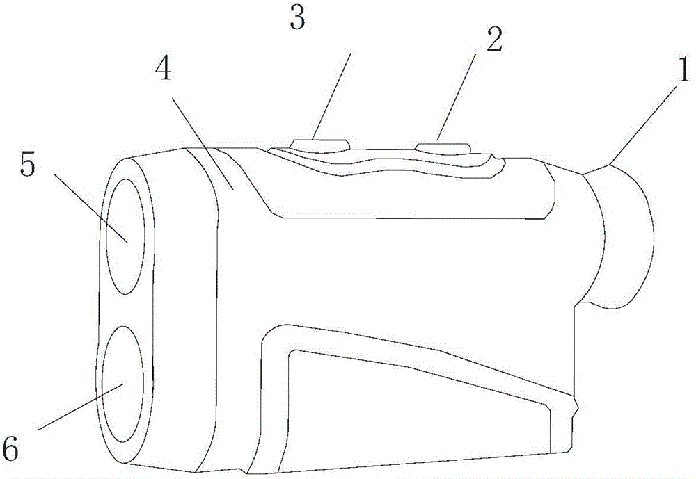
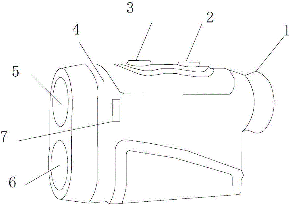
[0016] This application provides a laser rangefinder with a lens cover, such as figure 2 As shown, it includes an eyepiece 1 , an emission key 2 , a mode key 3 , a casing 4 , a laser emission objective lens 5 , a laser reception objective lens 6 , and a rotary knob 7 .

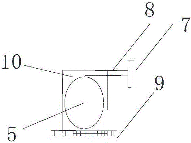
[0017] like figure 2 , image 3 As shown, it also includes a la...


PUM


Abstract

The invention discloses a laser range finder with an adjustable laser transmitting objective lens, which comprises an eyepiece, a transmitting key, a mode key, a shell, the laser transmitting objective lens, a laser receiving objective lens and a laser transmitting objective lens adjustment structure, wherein the laser transmitting objective lens adjustment structure comprises a threaded rod, a rotation button, a guide rail and a fixing frame; the laser transmitting objective lens is arranged on the fixing frame; the lower end of the fixing frame is connected with the guide rail and can slide on the guide rail horizontally; the upper end of the fixing frame is provided with a threaded hole, the threaded rod and the threaded hole are in threaded connection, the threaded rod and the guide rail are both fixed on the shell, and the threaded rod can rotate and drives the fixing frame to slide on the guide rail. Through the laser transmitting objective lens adjustment structure, slight adjustment of the position of the laser transmitting objective lens can be realized, and thus, when multiple nearby points are measured, quick positioning can be realized.

Description

technical field [0001] The invention relates to the technical field of laser tools, in particular to a laser rangefinder with an adjustable laser emitting objective lens. Background technique [0002] The laser rangefinder is an instrument that uses laser to accurately measure the distance of the target. When the laser range finder is working, it emits a very thin laser beam to the target, and the photoelectric element receives the laser beam reflected by the target. The timer measures the time from the launch to the reception of the laser beam, and calculates the distance from the observer to the target. [0003] With the advancement and development of science and technology, a variety of laser range finders have been developed. like figure 1 As shown, it is a laser rangefinder in the prior art, which includes an eyepiece 1 , an emission key 2 and a mode key 3 , a casing 4 , a laser emission objective lens 5 , and a laser reception objective lens 6 . When the above-menti...

Claims


Application Information

Patent Timeline
Patent Type & Authority Applications(China)
IPC IPC(8): G01S7/481
CPCG01S7/4814
Inventor 赵凌云
Owner 恩溢(天津)光电科技有限公司
Learn More