
Auxiliary measuring device and method for width of inner and outer ring flow channels between blades of cartridge receiver assembly

A technology of auxiliary measurement and external circulation, applied in the field of machinery, can solve the problems of heavy measurement workload and achieve the effects of improving measurement efficiency, reducing data processing time, and reducing measurement difficulty

Inactive Publication Date: 2021-01-05
AECC AVIATION POWER CO LTD
View PDF12 Cites 0 Cited by
  • Summary
  • Abstract
  • Description
  • Claims
  • Application Information

AI Technical Summary

Problems solved by technology

[0003] The purpose of the present invention is to overcome the shortcomings of large measurement workload when using a three-coordinate measuring machine to measure the actual value of the radius at a fixed point on the inner and outer ring flow channel surfaces, and to provide an auxiliary method for measuring the width of the inner and outer ring flow channels between the blades of the casing assembly. Measuring device and method

Method used


Image

  • Auxiliary measuring device and method for width of inner and outer ring flow channels between blades of cartridge receiver assembly
  • Auxiliary measuring device and method for width of inner and outer ring flow channels between blades of cartridge receiver assembly
  • Auxiliary measuring device and method for width of inner and outer ring flow channels between blades of cartridge receiver assembly

Examples


Embodiment Construction

[0041]In order to enable those skilled in the art to better understand the solutions of the present invention, the technical solutions in the embodiments of the present invention will be described clearly and completely with reference to the accompanying drawings in the embodiments of the present invention. Obviously, the described embodiments are only It is a part of the embodiments of the present invention, not all the embodiments. Based on the embodiments of the present invention, all other embodiments obtained by those of ordinary skill in the art without creative work shall fall within the protection scope of the present invention.

[0042]It should be noted that the terms "first" and "second" in the specification and claims of the present invention and the above-mentioned drawings are used to distinguish similar objects, and not necessarily used to describe a specific sequence or sequence. It should be understood that the data used in this way can be interchanged under appropriat...


PUM


Abstract

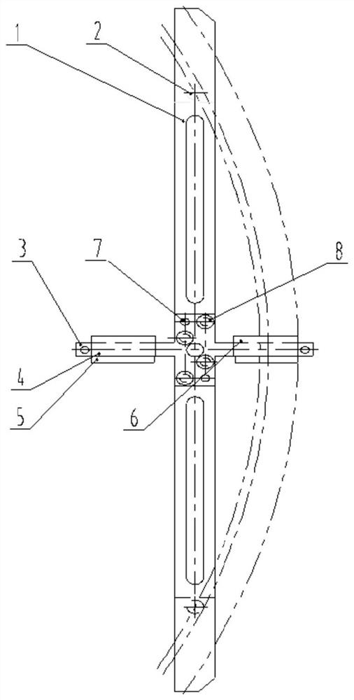
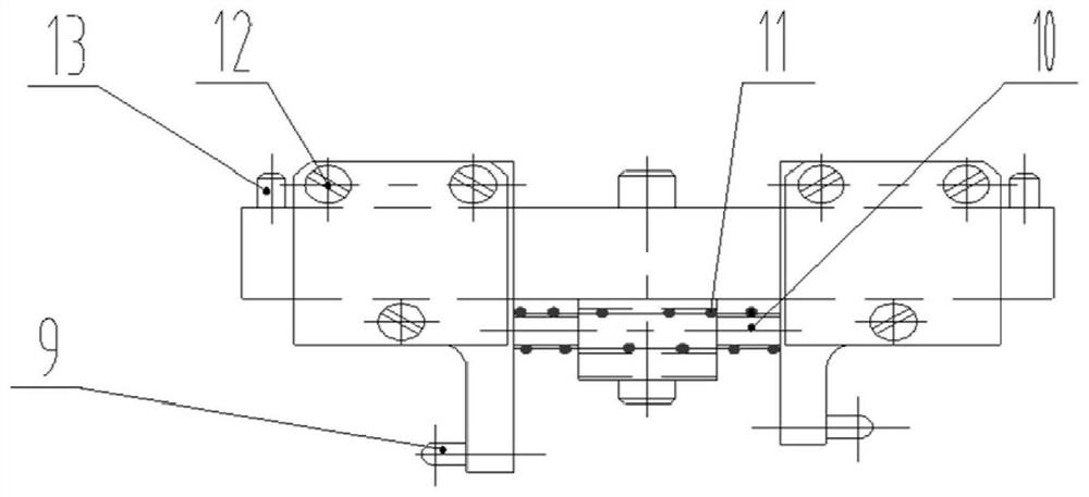
The invention discloses an auxiliary measuring device and method for the width of inner and outer ring flow channels between blades of a cartridge receiver assembly, and belongs to the field of machinery. The auxiliary measuring device comprises a cross-shaped positioning frame and a body; stepped pins are arranged at two ends of the positioning frame; a first sliding block is arranged on the bodylocated on one side of the positioning frame, a first sliding block cover plate is arranged on the first sliding block, a first clamping jaw is arranged on the bottom surface of the first sliding block cover plate, and a first positioning pin is arranged on the first clamping jaw; and the body positioned on the other side of the positioning frame has the same structure. According to the auxiliarymeasuring device, the stepped pins on the positioning frame are clamped on the outer ring to position the whole device, and the two stepped pins are clamped on the outer ring of the cartridge receiver; the body is provided with the sliding blocks and the sliding block covers, the two sliding block covers are respectively provided with the clamping jaws with the positioning pins, the positioning pins are used for positioning the flow channel walls, and rapid distance measurement can be achieved with the help of measuring tools like calipers.

Description

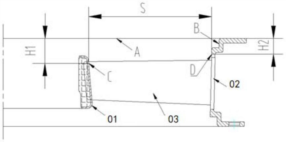
Technical field[0001]The invention belongs to the field of machinery, in particular to an auxiliary measuring device and method for the width of the inner and outer circulation channels between the blades of a casing assembly.Background technique[0002]Many aero-engine stator receiver components need to measure the width of the inner and outer circulation channels between the blades. Such parts are composed of outer ring, inner ring, and blades through welding. There are a large number of blades (generally more than 100 pieces), The narrow space between the blades brings a lot of data measurement and data processing work. At present, a three-coordinate measuring machine is usually used to measure the actual value of the radius at a fixed point on the inner and outer circulation channel surface, and the actual value of the channel width is calculated through the actual value of the corresponding point. The measurement workload is large and the data processing time is long.Summary of t...

Claims


Application Information

Patent Timeline
IPC IPC(8): G01B5/02G01B5/00
CPCG01B5/02G01B5/0004G01B5/003
Inventor 曹宗林张智景理任润娥吴经武党红武王强杨武
Owner AECC AVIATION POWER CO LTD
Learn More