
Power saving AC contactor utilizing controlled current

An AC contactor and current control technology, which is applied in relays, circuits, electrical components, etc., can solve the problems of high holding power, power loss, annoying AC noise, etc., and achieve the effect of suppressing transient voltage and saving electric energy

Active Publication Date: 2018-01-26
浙江大起电子股份有限公司
View PDF4 Cites 0 Cited by
  • Summary
  • Abstract
  • Description
  • Claims
  • Application Information

AI Technical Summary

Problems solved by technology

[0011] 1. Unnecessary power consumption: As mentioned above, in the pull-in and holding phases, the excitation coils of conventional AC contactors are all connected with the "same" AC voltage, which makes the holding power too large, resulting in unnecessary electric energy loss;
[0012] 2. Heating: The evil result of unnecessary power loss is "heating and heating". In severe cases, it will even burn the excitation coil of the conventional AC contactor;
[0013] 3. Annoying AC noise
[0018] This is one of the reasons why the "energy-saving AC contactor" referred to in the "prior art" has many research results but few practical applications.
[0019] 2. The "energy-saving AC contactor" referred to in the "existing technology" is generally equipped with a control circuit, and the control current is only used for the control circuit without comprehensive utilization

Method used


Image

  • Power saving AC contactor utilizing controlled current
  • Power saving AC contactor utilizing controlled current
  • Power saving AC contactor utilizing controlled current

Examples


Embodiment Construction

[0048] Below in conjunction with accompanying drawing, illustrate the embodiment of the present invention.

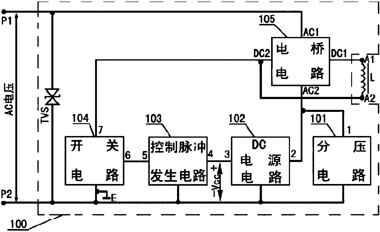
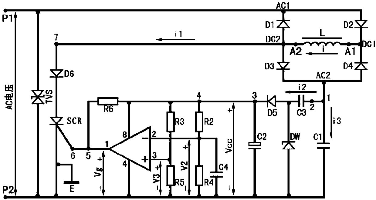
[0049] figure 2 It is a block diagram of the principle of the present invention, image 3 It is the schematic circuit diagram of embodiment 1. figure 2 Middle: L is the excitation coil in a conventional AC contactor, and A1 and A2 are its two connection ports; the dotted line box 100 represents the electronic unit 100 of the present invention.

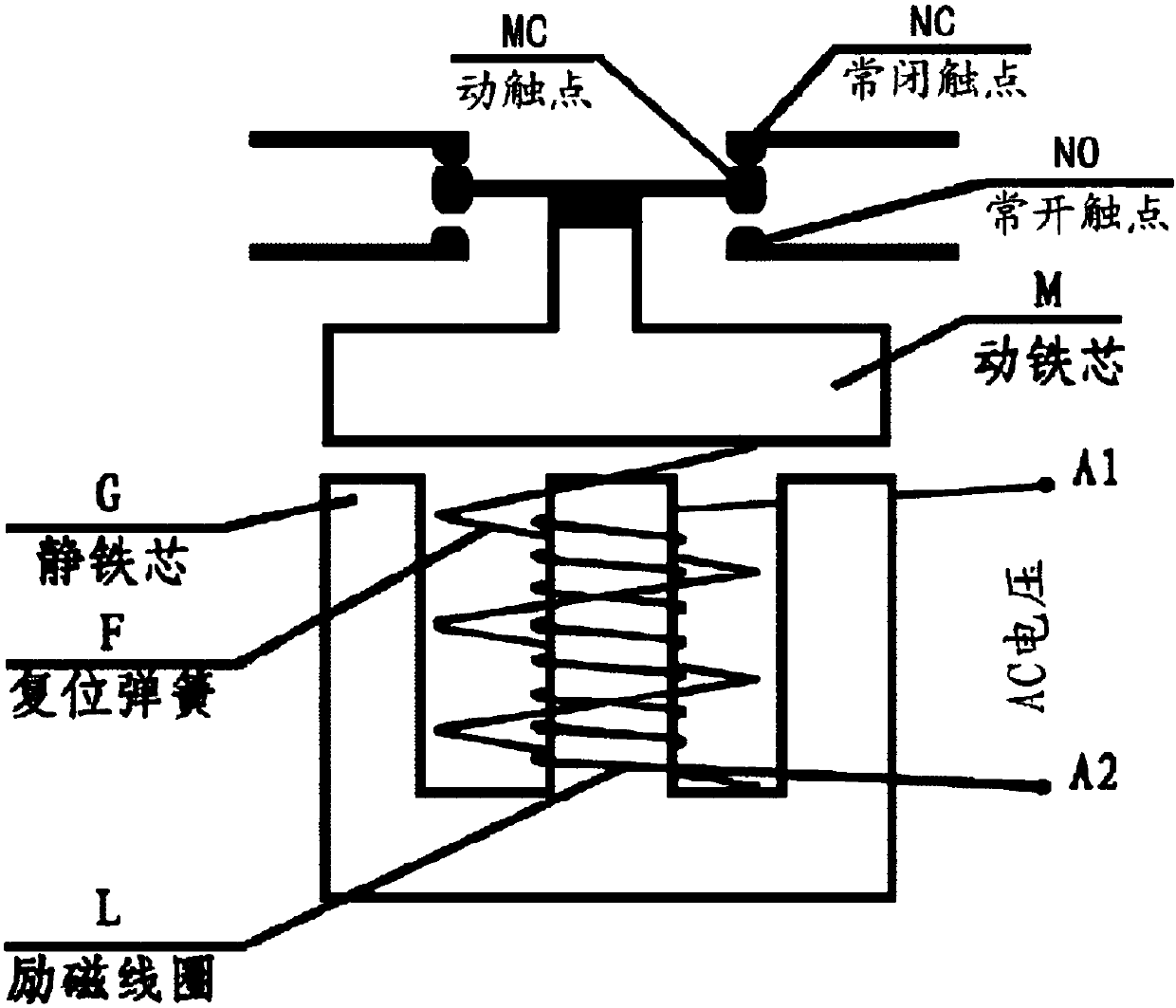
[0050] combine figure 1 , figure 2 : A power-saving AC contactor using control current, including a moving contact MC, a normally closed contact NC, a normally open contact NO, a moving iron core M, a static iron core G, a return spring F, and an excitation coil L. It consists of two parts, a conventional AC contactor and an electronic unit 100, characterized in that the electronic unit 100 is composed of a transient voltage suppression diode TVS, a voltage divider circuit 101, a DC power supply circuit 102, a control pul...


PUM


Abstract

The invention discloses an energy-saving AC contactor employing a control current, and the contactor comprises a conventional AC contactor and an electronic unit 100, wherein the conventional AC contactor consists of a movable contact MC, a normally-closed contact NC, a normally-opened contact NO, a moving iron core M, a static iron core G, a reset spring F, and an excitation spring L. The contact is characterized in that the electronic unit 100 consists of a transient voltage suppression diode TVS, a voltage-dividing circuit 101, a DC power circuit 102, a control pulse generation circuit 103, a switching circuit 104, a bridge circuit 105, and a common end E.

Description

technical field [0001] The invention relates to the field of low-voltage electrical appliances, in particular to a "power-saving AC contactor using control current" which can efficiently save electricity and has the function of suppressing transient voltage. Background technique [0002] Alternating Current Contactor (Alternating Current Contactor) is a low-voltage electrical appliance that is widely used. As of 2015, there are more than one billion AC contactors running online in my country, and the number is increasing at an annual rate of 80 million. Its working principle is to use the electromagnet to drive the movable contact to separate or close the normally closed contact or normally open contact, so as to cut off or connect the circuit. It is suitable for starting or controlling three-phase induction motors and other electrical equipment. [0003] figure 1 It is a working principle diagram of a conventional AC contactor. This conventional AC contactor is mainly co...

Claims


Application Information

Patent Timeline
Patent Type & Authority Patents(China)
IPC IPC(8): H01H47/02
CPCH01H47/02
Inventor 孙浙胜汪孟金朱亮
Owner 浙江大起电子股份有限公司
Learn More