Directive power supply equipment

A technology for power supply equipment and power supply holes, which is applied to circuits, electrical components, coupling devices, etc., can solve the problems of inability to realize automatic implementation, inability to guarantee, and inability to guarantee the reliability and stability of electrical bonding

Inactive Publication Date: 2016-09-28
龚云新
View PDF3 Cites 6 Cited by
  • Summary
  • Abstract
  • Description
  • Claims
  • Application Information

AI Technical Summary

Problems solved by technology

[0002] Reliable and convenient electrical connection is required between some electrical equipment and power supply equipment; however, in the electrical connection of some existing power supply equipment, it cannot guarantee the reliability and stability of the electrical connection; or, in realizing a more reliable electrical connectio...

Method used


Image

  • Directive power supply equipment

Examples


Embodiment Construction

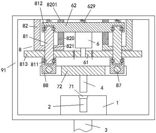
[0007] Combine below figure 1 The present invention will be described in detail.

[0008] A guided power supply device according to an embodiment includes a housing 91, and a power supply jack device 1 arranged on the lower side wall of the housing 91, and a utility model arranged on the upper side wall of the housing 91 An electric plug device. The power supply jack device 1 includes a power supply cable 3 and a power supply hole 2 for electrically connecting with the power plug device. The power plug device includes a power supply that is fixed to the upper side wall of the housing 91 Two top pressure screw assemblies 8 connected, the two top pressure screw assemblies 8 are arranged symmetrically with respect to the longitudinal axis of the housing 91 and each include: a thread fixed on the upper side wall of the housing 91 The fixing sleeve 82, the top pressure screw 81 threadedly fitted with the threaded hole 821 in the lower end wall of the threaded fixing sleeve 82, and th...


PUM


Abstract

The invention provides directive power supply equipment comprising a shell (91), a power supply jack device (1) which is arranged on the lower side wall of the shell (91) and a power utilization plug device which is arranged on the upper side wall of the shell (91). The power supply jack device (1) comprises a power supply cable (3) and a power supply hole (2) which is electrically connected with the power utilization plug device. The power utilization plug device comprises two abutting screw rod components (8) which are fixedly connected with the upper side wall of the shell (91). The two abutting screw rod components (8) are symmetrically arranged about the longitudinal axis of the shell (91), and each abutting screw rod component (8) comprises a threaded fixing sleeve (82) which is fixed on the upper side wall of the shell (91) and an abutting screw rod (81) which is matched with the threaded hole (821) in the lower end wall of the threaded fixing sleeve (82) in a threaded way.

Description

Technical field [0001] The invention relates to the field of power supply equipment, in particular to a oriented power supply equipment. Background technique [0002] Some electrical equipment and power supply equipment require reliable and convenient electrical connections; however, some existing electrical connections of power supply equipment cannot guarantee the reliability and stability of the electrical connection; or, in the realization of more reliable electrical connections In the connected power supply equipment, it cannot be automated. Moreover, more importantly, it is not possible to ensure that the position of the socket and the plunger is locked while mechanically ensuring the stable joint of the socket and the plunger before the engagement and the position lock after the engagement. Summary of the invention [0003] The purpose of the present invention is to provide a oriented power supply device which can overcome the defects in the prior art. [0004] A oriented p...

Claims


Application Information

Patent Timeline
IPC IPC(8): H01R13/629H01R13/639H01R13/66
CPCH01R13/629H01R13/639H01R13/665
Inventor 龚云新
Owner 龚云新
Why Eureka
Try Eureka