Shielding pump with inducting wheel

A technology of inducer and shielded pump, applied in pump, components of pumping device for elastic fluid, pump device, etc., can solve problems such as impeller cavitation

Inactive Publication Date: 2016-10-05
杨建
View PDF9 Cites 5 Cited by
  • Summary
  • Abstract
  • Description
  • Claims
  • Application Information

AI Technical Summary

Problems solved by technology

However, the impeller of the existing canned pump is mainly in the form of a centrifu

Method used


Image

  • Shielding pump with inducting wheel
  • Shielding pump with inducting wheel
  • Shielding pump with inducting wheel

Examples


Embodiment Construction

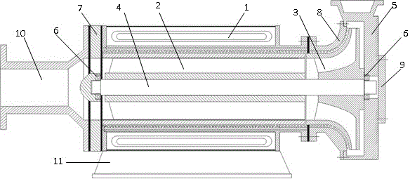
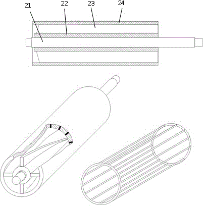
[0012] The following describes the specific implementation of the invention of a canned pump with an inducer with reference to the accompanying drawings. Such as Figure 1-Figure 3 The canned pump with inducer shown includes stator 1 with coil winding, rotor 2 with axial inducer and squirrel cage structure, centrifugal impeller 3, connecting shaft 4, centrifugal pump casing 5, bearing 6, bearing bracket 7 , the pump casing front cover 8, the pump casing rear cover 9, the inlet guide pipe 10, and the base 11. An interlayer of non-magnetic material is set between the stator 1 with coil winding and the rotor 2 with axial inducer and squirrel cage structure, and the rotor 2 with axial inducer and squirrel cage structure is composed of shaft 21, hub 22, the blade 23 and the cylindrical outer ring 24 containing the squirrel cage are formed. The inducer 2 and the centrifugal impeller 3 are fixed in series on the same shaft. The outer surface of the hub 22 of the rotor 2 is fixedly...


PUM


Abstract

The invention relates to a shielding pump with an inducting wheel. The shielding pump comprises a stator (1) having a coil winding, a rotor (2) having an axial inducting wheel and a cage mouse structure, a centrifugal impeller (3), a connecting shaft (4), a centrifugal pump shell (5), a bearing (6), a bearing support (7), a pump shell front cover plate (8), a pump shell back cover plate (9), an inlet flow-guide pipe (10) and a base (11). During operation of the shielding pump, coils of the stator generate a rotary magnetic field and a mouse cage is driven to rotate such that an axial blade and a centrifugal blade rotate to drive fluid to flow. A motor rotor of the shielding pump is changed to a structure containing the axial inducting wheel. The top of a conventional inducting wheel, namely, the top of the axial-flow blade is provided with a cylindrical structure in order to eliminate leakage loss of a blade tip. Due to an annular or spiral groove in the pump, leakage loss is reduced. While ensuring non-leakage feature of the shielding pump, driving force of the overall pump is added so that efficiency of the overall pump is increased and cavitation erosion resistance of the pump is improved.

Description

technical field [0001] The invention relates to fluid machinery, in particular to a canned pump with an inducer. Background technique [0002] A canned pump is a leak-free centrifugal pump. Usually, there is circulating cooling water between the motor rotor and the motor stator, which can take away part of the heat generated by the motor when it is working, and ensure the normal operation of the motor. However, the impeller of the existing canned pump is mainly in the form of a centrifugal pump, and the impeller may also produce cavitation under some working conditions. In order to reduce the impact of cavitation in the design of centrifugal pumps, an inducer is usually installed in front of the centrifugal impeller. A cylindrical structure is designed to eliminate the leakage loss of the blade tip, and the gap in the pump that may cause leakage loss from the high-pressure end to the low-pressure end is designed with an annular or spiral groove. The canned pump motor is p...

Claims


Application Information

Patent Timeline
IPC IPC(8): F04D13/06F04D29/18F04D29/66F04D29/08
Inventor 杨建
Owner 杨建
Why Eureka
Try Eureka