

Heat demand estimation device and method, facility control device, method and system
A technology for equipment control and demand, applied in heating and ventilation control systems, lighting and heating equipment, heating methods, etc., can solve problems such as inability to apply, high price of flow sensors, troublesome flow sensor settings, etc.
- Summary
- Abstract
- Description
- Claims
- Application Information
AI Technical Summary
Problems solved by technology
Method used
Image

Examples
Embodiment approach 1
[0071] when based on Figure 1 to Figure 6 One embodiment (Embodiment 1) of the present invention will be described as follows.
[0072] (Outline of equipment control system)
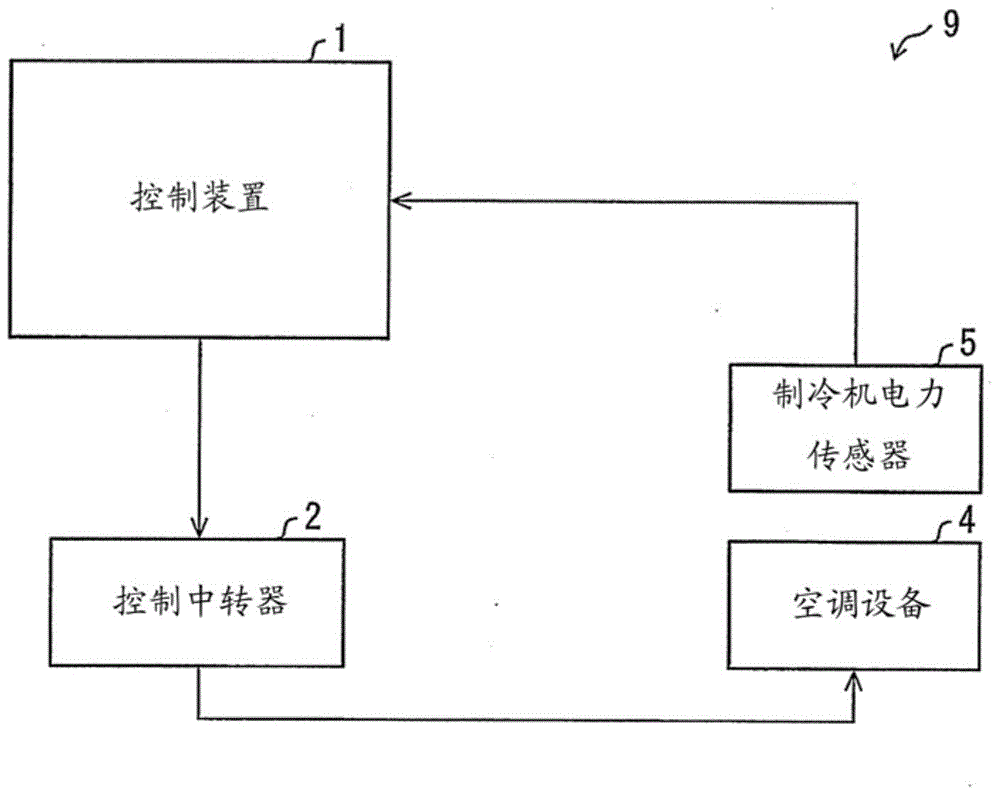
[0073] First, based on figure 2 The outline of the device control system of this embodiment will be described. figure 2 It is a block diagram showing an example of the structure of the equipment control system 9 of Embodiment 1.
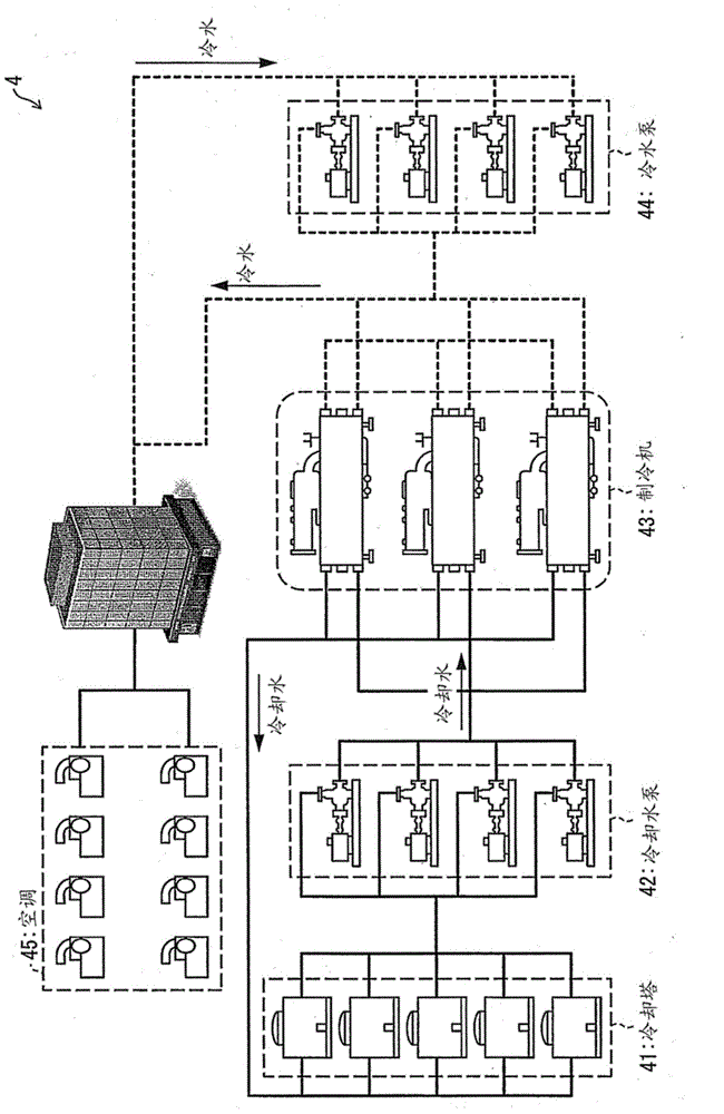
[0074] Such as figure 2 As shown, the equipment control system 9 includes: a control device (heat demand estimation device, equipment control device) 1 , a control relay 2 , an air conditioner 4 , and a refrigerator power sensor 5 .
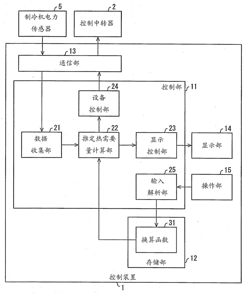
[0075] (control device)
[0076] The control device 1 estimates the heat demand of the air conditioner 4 based on the data acquired from the refrigerator power sensor 5 , and controls the air conditioner 4 based on the estimated heat demand. Specifically, the control device 1 transmits a control signal to each device of the air condition...
Embodiment approach 2
[0132] when based on Figure 7 ~ Figure 11 Another embodiment (Embodiment 2) of the present invention will be described as follows. In addition, for convenience of explanation, components having the same functions as those shown in Embodiment 1 above are denoted by the same reference numerals and their descriptions are omitted.
[0133] In the second embodiment, by learning and deriving the above-mentioned conversion function 31 , the estimation error of the estimated heat demand is reduced compared with the first embodiment. Hereinafter, in Embodiment 2, differences from Embodiment 1 will be mainly described.
[0134] (Outline of equipment control system)
[0135] First, based on Figure 7 The outline of the device control system of this embodiment will be described. Figure 7 It is a block diagram showing an example of the structure of the equipment control system 9a of Embodiment 2.
[0136] Such as Figure 7 As shown, compared with the equipment control system 9 , th...
Embodiment approach 3
[0174] when based on Figure 12 to Figure 14 Another embodiment (Embodiment 3) of the present invention will be described as follows. In addition, for convenience of explanation, components having the same functions as those shown in Embodiment 1 and Embodiment 2 above are given the same reference numerals and their descriptions are omitted.
[0175] In Embodiment 2, since no flow sensor is provided to estimate the cold water flow rate, it is necessary to fix the cold water flow rate (set flow rate of the cold water pump 44). However, in order to maintain the comfort of the living room or maintain the equipment, the air conditioner 4 may change the operation content of the air conditioner through the judgment of the on-site operator or the control of the existing system. Therefore, the set flow rate of the cold water pump 44 may not be fixed, and the learning process may not be performed.
[0176] Therefore, in the present embodiment, even if the cold water flow rate fluctua...
PUM
 Abstract
Description
Claims
Application Information