Visual positioning system and method based on high-reflective infrared identification

A visual positioning and high-reflective technology, applied in the field of visual positioning systems, can solve problems such as inconvenient layout, easy failure, complex structure, etc., and achieve the effect of simple structure, no delay, and no power supply

Active Publication Date: 2016-10-05
BEIJING ANTVR TECH
View PDF5 Cites 22 Cited by
  • Summary
  • Abstract
  • Description
  • Claims
  • Application Information

AI Technical Summary

Problems solved by technology

[0003] At present, the main marking points used are active and active marking points. These active and active marking points are assigned with coordinate information and must include modules such as signal transmitters inside. If they are used for positioning in a large space, a large number of such points are required. Active active marking points, in addition, have the disadvantages of complex structure, prone to failure, inconvenient layout and positioning delay, etc.

Method used


Image

  • Visual positioning system and method based on high-reflective infrared identification
  • Visual positioning system and method based on high-reflective infrared identification
  • Visual positioning system and method based on high-reflective infrared identification

Examples


Embodiment Construction

[0029] The objects and functions of the present invention and methods for achieving the objects and functions will be clarified by referring to the exemplary embodiments. However, the present invention is not limited to the exemplary embodiments disclosed below; it can be implemented in various forms. The essence of the description is only to help those skilled in the relevant art comprehensively understand the specific details of the present invention.

[0030] Hereinafter, embodiments of the present invention will be described with reference to the accompanying drawings. In the drawings, the same reference numerals represent the same or similar components, or the same or similar steps.

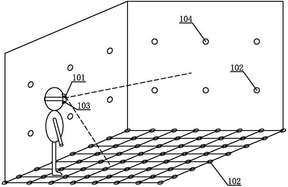
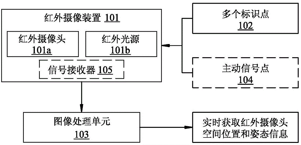
[0031] figure 1 with figure 2 An application schematic diagram and a system frame diagram of a visual positioning system based on an infrared high-reflective mark according to the present invention are respectively shown. The visual positioning system 100 of the present invention includ...


PUM


Abstract

The invention provides a visual positioning system and method based on high-reflective infrared identification. The visual positioning system comprises a plurality of identification points, an infrared camera device and an image processing module. The multiple identification points are source-free passive identification points made of an infrared high-reflective material and arranged on a plane needing to be positioned at equal intervals. The infrared camera device is used for shooting reflective images of the identification points. The image processing unit is used for obtaining relative positions and relative posture changes by acquiring and analyzing information of the images taken by the infrared camera. The invention further provides a visual positioning method based on high-reflective infrared identification. The visual positioning system and method have the advantages that the structure is simple, power supplying is not needed, the cost is low, delay does not exist, and positioning precision is high.

Description

technical field [0001] The invention relates to a visual positioning system and method, in particular to a visual positioning system and method based on an infrared high-reflective mark. Background technique [0002] Usually, in the field of computer vision, especially in the field of virtual reality, the coordinate information and posture information of the image acquisition device (such as a camera) are located by processing and analyzing images of marked points in the environment. [0003] At present, the main marking points used are active and active marking points. These active and active marking points are assigned with coordinate information and must include modules such as signal transmitters inside. If they are used for positioning in a large space, a large number of such points are required. Active active marking points, in addition, have disadvantages such as relatively complex structure, prone to failure, inconvenient layout and placement, and positioning delay. ...

Claims


Application Information

Patent Timeline
Patent Type & Authority Applications(China)
IPC IPC(8): G01C11/00G01C11/12
CPCG01C11/00G01C11/12G01C21/20G01S17/46G01S17/50G06T7/246G06T7/73G06T2207/10048G01S17/86G01C11/28
Inventor 覃政
Owner BEIJING ANTVR TECH
Why Eureka
Try Eureka