
EPR microwave cavity for small magnet airgaps

A microwave and cavity technology, applied in the direction of using electron paramagnetic resonance for measurement, electrical components, measurement of magnetic variables, etc.

Active Publication Date: 2016-10-05
BRUKER BIOSPIN
View PDF12 Cites 8 Cited by
  • Summary
  • Abstract
  • Description
  • Claims
  • Application Information

AI Technical Summary

Problems solved by technology

However, it is known that higher fill factors in EPR resonators require a compromise in the Q-factor of the cavity, which linearly determines the EPR signal strength from the sample
It is also known that limiting the sample volume requires a linear tradeoff in EPR signal strength

Method used


Image

  • EPR microwave cavity for small magnet airgaps
  • EPR microwave cavity for small magnet airgaps
  • EPR microwave cavity for small magnet airgaps

Examples


Embodiment Construction

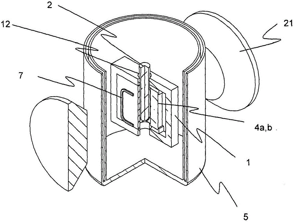
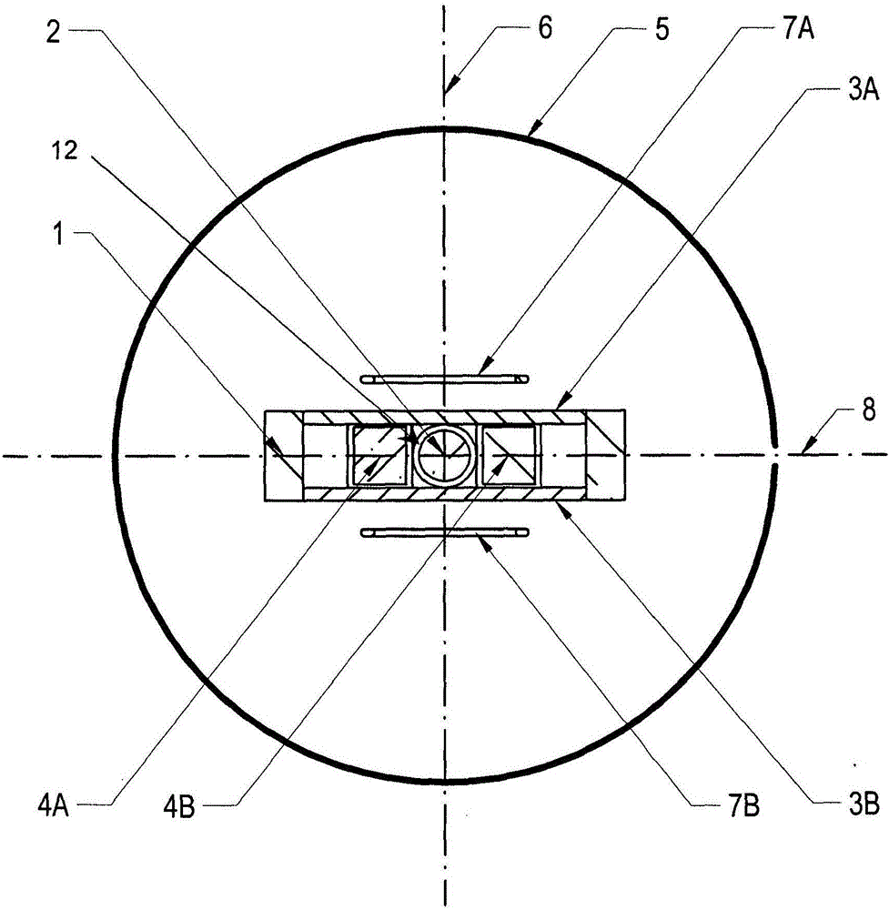
[0052] exist figure 1 A simplified example of a novel EPR experimental setup according to the present invention is shown in . An EPR experiment showing a flat microwave cavity 1 loaded with dielectrics 4a,b, together with a variable temperature cryostat 5, the poles 21 of an external magnet forming the main static magnetic field and responsible for the formation of a modulated magnetic field throughout the EPR cavity and a paramagnetic sample 2 The modulating coil 7. Samples mostly consist of tubes that hold the substance to be measured. When describing the characteristics of the resonator in relation to the position of the sample, it is understood that this is equivalent to the space provided to accommodate the sample. All other details about the mechanical or standard implementation of microwaves (various supports, coaxial microwave launch lines and microwave coupling structures necessary to excite microwave resonances relevant to EPR use) are suppressed for clarity.

[...


PUM


Abstract

The present invention relates to an EPR microwave cavity for small magnet airgaps. A microwave resonator for an EPR probe head has a metal cavity body for supporting an electromagnetic microwave resonance mode, the electromagnetic microwave resonance mode having an even number of local maxima of microwave electric field energy, the metal cavity body having an opening for inserting a smaple tube to a center position of the resonator, wherein a center of the opening and a center position of the resonator define an x-axis, the metal cavity body also having an opening for transmitting microwave radiation into the resonator; and two substantially identical dielectric elements located symmetrically with respect to an E-field nodal plane containing the x-axis and a z-axis perpendicular to the x-axis, wherein each dielectric element is geometrically formed and positioned to provide an equal overlap with a local maximum of the microwave electric field energy. The microwave resonant cavity has a thin planar shape for an EPR probe head. The resonator is loaded with two dielectric elements, of identical shape and physical properties, placed symmetrically relative to the central EPR sample.

Description

technical field [0001] The present invention relates to a microwave resonator for EPR (= "Electron Paramagnetic Resonance") probes, the microwave resonator comprises: a metallic cavity body supporting electromagnetic microwave resonant modes with an even number of microwave electric field energies a local maximum; at least one opening for inserting the sample tube into a central position of the resonator, the center of the opening and the central position of the resonator defining an x-axis; at least one opening for emitting microwave radiation into said resonator ; at least two identical dielectric elements positioned symmetrically to a plane called the "E-field nodal plane" containing the x-axis and the z-axis perpendicular to the x-axis. [0002] A device of this type is known from US-A 3,757,204. Background technique [0003] In EPR methods it is often desired or even necessary to perform measurements under variable temperature conditions on the sample. A device that i...

Claims


Application Information

Patent Timeline
Patent Type & Authority Applications(China)
IPC IPC(8): H01P1/207
CPCH01P1/207G01R33/345G01R33/343G01R33/60H01P7/10
Inventor I·普瑞瑟卡鲁P·霍尔弗尔
Owner BRUKER BIOSPIN
Learn More