Determining method and device for macro and micro base station arrangement

A determination method and micro base station technology, applied in the field of mobile communication, can solve problems such as unreasonable deployment methods of macro and micro base stations

Active Publication Date: 2016-10-05
CHINA MOBILE COMM GRP CO LTD
View PDF3 Cites 3 Cited by
  • Summary
  • Abstract
  • Description
  • Claims
  • Application Information

AI Technical Summary

Problems solved by technology

[0005] Embodiments of the present invention provide a method and equipment for determining the deployment of macro and micro base stations to solve the problem of unreasonable macro and micro base station deployment methods in the prior art

Method used


Image

  • Determining method and device for macro and micro base station arrangement
  • Determining method and device for macro and micro base station arrangement
  • Determining method and device for macro and micro base station arrangement

Examples


Embodiment 1

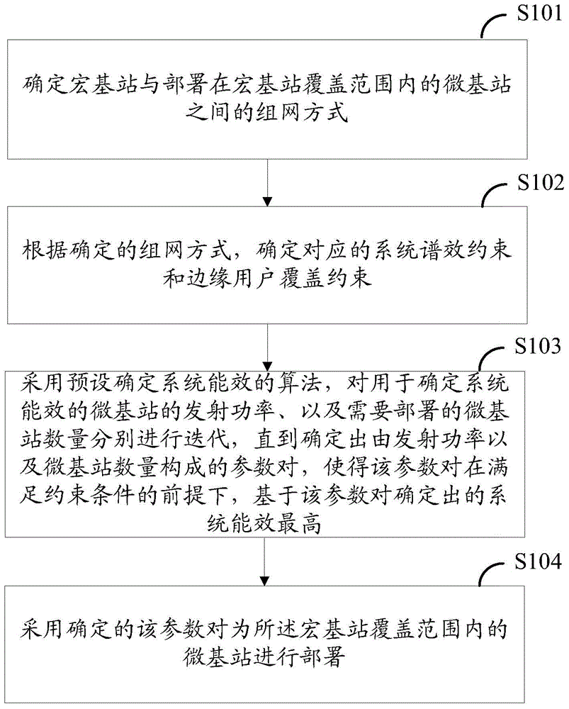
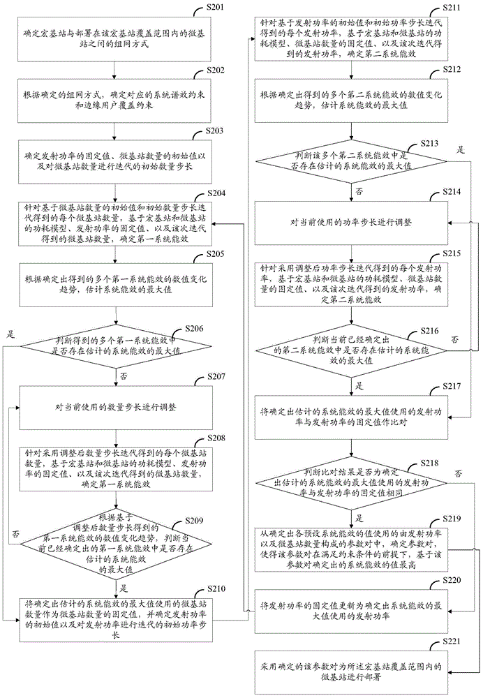
[0040] In Embodiment 1 of the present invention, a method for determining the deployment of macro and micro base stations is provided, such as figure 2 As shown, in Embodiment 1, firstly, the value of the transmission power of the micro base station is fixed, and the number of micro base stations is iterated by using the initial number step size, and then the fixed value of the number of micro base stations is determined from the number of micro base stations obtained through iteration, and the The transmission power of the micro base station is iterated, which specifically includes the following steps:

[0041] S201. Determine a networking mode between a macro base station and a micro base station deployed within the coverage of the macro base station.

[0042] Further, in this step, the macro base station and the micro base stations deployed within the coverage area of ​​the macro base station can be networked in the same-frequency networking manner, or in a different-frequ...

Embodiment 2

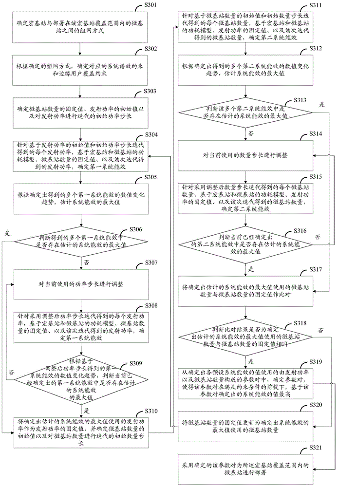
[0110] In Embodiment 2 of the present invention, a method for determining the deployment of macro and micro base stations is provided, such as image 3 As shown, in Embodiment 2, firstly, the value of the number of micro base stations is fixed, and the initial power step is used to iterate the transmit power of the micro base stations, and then the fixed value of the transmit power is determined from the transmit power obtained through iteration, and the micro base station The quantity is iterated, which specifically includes the following steps:

[0111] S301. Determine a networking mode between the macro base station and the micro base station deployed within the coverage of the macro base station.

[0112] Further, in this step, the macro base station and the micro base stations deployed within the coverage area of ​​the macro base station can be networked in the same-frequency networking manner, or in a different-frequency networking manner.

[0113] S302. According to th...


PUM


Abstract

The invention provides a determining method and device for macro and micro base station arrangement, and relates to the field of mobile communication. The networking manner between a macro base station and micro stations within the coverage range of the macro station is determined; and according to the determined networking manner, corresponding system spectrum-effect constraint and an edge user coverage constraint; a preset algorithm to determine the system efficacy, the emission power of the micro stations for determining the system efficacy and the amount of the micro stations which need arrangement are iterated till a parameter pair composed of the emission power and the amount of the micro stations is determined, and the system efficacy determined by the parameter pair is highest on the premise that the parameter pair satisfies the constraints, namely the emission power and the amount, of the micro stations, forming the parameter pair satisfy the system spectrum-effect constraint, and the amount of the micro stations satisfies the edge user coverage constraint; and the determined parameter pair is used to arrange the micro stations within the coverage range of the macro station. Compared with the prior art, the method and device are more reasonably.

Description

technical field [0001] The present invention relates to the technical field of mobile communication, and in particular to a method and equipment for determining deployment of macro and micro base stations. Background technique [0002] With the rapid development of mobile communication technology, people's demand for wireless data and multimedia business services is showing explosive growth. Simple deployment of macro base stations is increasingly unable to meet people's needs. In the existing technology, by combining micro base stations with The macro base station is combined with the deployment scheme to improve system capacity and system quality. That is to say, for each macro base station, a certain number of micro base stations are deployed around the macro base station to meet the needs of users of the macro base station. [0003] During specific implementation, the geographical area to be analyzed is divided into grids of different regions according to a certain reso...

Claims


Application Information

Patent Timeline
Patent Type & Authority Applications(China)
IPC IPC(8): H04W16/26
CPCY02D30/70
Inventor 何金薇徐志昆陈亚迷易芝玲任琦范建存罗新民
Owner CHINA MOBILE COMM GRP CO LTD
Why Eureka
Try Eureka