Milk cow forage stirring device

A stirring device and cow feed technology, applied to mixers with rotating stirring devices, mixer accessories, transportation and packaging, etc., can solve problems such as high temperature, cost increase, and damage to feed nutrients, so as to reduce costs and improve efficiency , reduce the effect of nutrient loss

Active Publication Date: 2016-10-12
湖北俏牛儿牧业有限公司
View PDF4 Cites 1 Cited by
  • Summary
  • Abstract
  • Description
  • Claims
  • Application Information

AI Technical Summary

Problems solved by technology

[0002] The existing milk cow feed mixing device has a simple structure and a single function, and it mainly has the following disadvantages: 1. During the feed mixing process, it is impossible to dry out the residual residues (such as gravel, etc.) in the feed, which makes The produced feed also needs to go through a special screening process, which not only wastes time and manpower, but also increases energy consumption and costs; 2. During the stirring process, the high-speed stirring of the stirring blades will generate high temperature, which will destroy the nutritional content of the feed , especially the feed located at the bottom edge of the mixing tank is not only in the dead corner of mixing, but also destroyed by high temperature

Method used


Image

  • Milk cow forage stirring device

Examples


Embodiment Construction

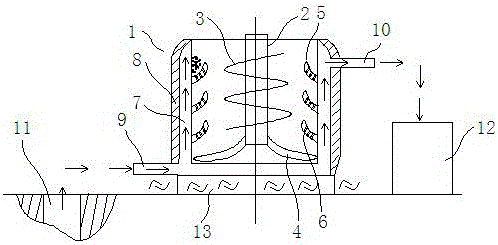
[0013] Accompanying drawing is a kind of specific embodiment of the present invention.

[0014] like figure 1 As shown in , this embodiment includes a stirring tank 1, a stirring shaft 2 is arranged in the stirring tank, a propeller blade 3 is arranged on the stirring shaft, and a turning paddle 4 positioned at the bottom of the propeller blade is also arranged on the stirring shaft, the turning paddle The leaves extend from the stirring shaft to the edge of the bottom of the stirring tank so as to turn up the feed at the bottom of the stirring tank; the inner wall of the stirring tank is also evenly distributed with sieve teeth 5, and the tooth surface of the sieve teeth is provided with sieve holes 6. The feed turned up by the turning blades and propeller blades falls on the sieve teeth, and the impurities can be screened out through the sieve holes; the outer ring of the mixing tank is provided with a low-temperature interlayer 7, and the outer ring of the low-temperature i...


PUM


Abstract

The invention relates to a milk cow forage stirring device. The milk cow forage stirring device comprises a stirring tank. A stirring shaft is arranged in the stirring tank. A spiral paddle is arranged on the stirring shaft. A turning paddle located below the spiral paddle is arranged on the stirring shaft. The turning paddle stretches to the edge of the bottom of the stirring tank from the stirring shaft. Screening teeth are evenly distributed on the inner wall of the stirring tank, and screen holes are formed in the tooth surfaces of the screening teeth. A low-temperature interlayer is arranged on the outer ring of the stirring tank, and a heat insulating layer is arranged on the outer ring of the low-temperature interlayer. According to the milk cow forage stirring device, impurities left in forage can be screened out while the forage is stirred in the stirring tank, efficiency is improved, and cost is reduced; the forage on the edge of the bottom of the stirring tank can be turned up by the turning paddle, and no stirring dead corner is left; through the arrangement of the low-temperature interlayer, nutrition loss caused by high-temperature damage to the forage can be relieved.

Description

technical field [0001] The invention relates to the field of dairy cow feeding, in particular to a dairy cow feed stirring device. Background technique [0002] The existing milk cow feed mixing device has a simple structure and a single function, and it mainly has the following disadvantages: 1. During the feed mixing process, it is impossible to dry out the residual residues (such as gravel, etc.) in the feed, which makes The produced feed also needs to go through a special screening process, which not only wastes time and manpower, but also increases energy consumption and costs; 2. During the stirring process, the high-speed stirring of the stirring blades will generate high temperature, which will destroy the nutritional content of the feed , especially the feed located at the bottom edge of the mixing tank is not only in the dead corner of mixing, but also destroyed by high temperature. Contents of the invention [0003] In order to solve the above problems, the pre...

Claims


Application Information

Patent Timeline
Patent Type & Authority Applications(China)
IPC IPC(8): B01F7/16B01F15/06
CPCB01F27/1921B01F27/80B01F35/53B01F2035/98B01F35/92B01F2101/18
Inventor 李鑫
Owner 湖北俏牛儿牧业有限公司
Why Eureka
Try Eureka