Cutter abrasion monitoring method based on cutting force model

A tool wear and cutting tool technology, applied in the direction of manufacturing tools, measuring/indicating equipment, metal processing machinery parts, etc., can solve the problems of unstable threshold value, tool wear prone to error, misjudgment, etc., to achieve accurate results and simple calculation process Effect

Active Publication Date: 2016-10-12
太仓鑫祥金属制品有限公司 +1
View PDF4 Cites 6 Cited by
  • Summary
  • Abstract
  • Description
  • Claims
  • Application Information

AI Technical Summary

Problems solved by technology

However, in actual monitoring, due to the interference of vibration and random noise, it is easy to make mistakes when using this method to judge tool wear, resulting in misjudgment
Moreover, due to the uncertainty of the boundary between normal wear and abnormal wear of the tool, it is difficult to determine the threshold in advance. It must be determined based on experience and many experiments, and the threshold is not stable in different occasions.

Method used


Image

  • Cutter abrasion monitoring method based on cutting force model
  • Cutter abrasion monitoring method based on cutting force model
  • Cutter abrasion monitoring method based on cutting force model

Examples


Embodiment Construction

[0029] The present invention will be further described in detail below in conjunction with the examples, but the present examples are not intended to limit the present invention, and all similar methods and similar changes of the present invention should be included in the protection scope of the present invention.

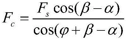
[0030] In the process of establishing the cutting force model of the tool, the cutting force under the action of the sharp tool caused by the formation of chips is firstly calculated by using the non-equal shear zone model, and then the plowing force caused by the blunt cutting edge is calculated, and the The comprehensive superposition of the two can get the cutting force when considering the blunt cutting edge.

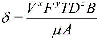
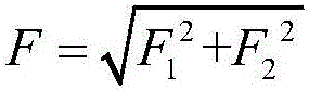
[0031] In the process of chip formation, the force required for shear slip is transmitted by the rake face of the tool and through the chips. Since the chips flow out along the rake face at a certain speed, the cutting force should meet the requirements ...


PUM


Abstract

The invention discloses a cutter abrasion monitoring method based on a cutting force model. The cutter abrasion monitoring method is used for conducting real-time online monitoring on the abrasion loss of a cutting tool. The cutter abrasion monitoring method is characterized by comprising the steps that 1, cutting force caused by chip forming under the action of a sharp cutter in the cutting process is calculated by means of a non-equant shearing region model; 2, plowing force caused by cutting edge roundness in the cutting process is calculated; 3, cutter cutting force is obtained according to the determined cutting force under the action of the sharp cutter and the determined plowing force caused by cutting edge roundness; 4, a cutter abrasion monitoring model is established according to the obtained cutter cutting force, and therefore real-time monitoring on cutter abrasion is achieved. By means of the cutter abrasion monitoring method based on the cutting force model, the cutter abrasion state can be accurately represented, monitoring on the cutter abrasion can be achieved by monitoring the cutting force, and therefore real-time online and accurate monitoring of the cutter abrasion is achieved.

Description

technical field [0001] The invention belongs to the field of tool wear monitoring and relates to a tool wear monitoring method based on a cutting force model. Background technique [0002] During the cutting process of the workpiece, the tool will be worn, and the wear of the tool will cause the geometric shape of the tool to change, so that the workpiece will have a dimensional deviation and affect the processing quality of the workpiece. In order to avoid excessive deviation of the workpiece and improve the processing quality, it is necessary to monitor the wear of the tool, and determine whether to change the tool according to the monitoring results. [0003] The commonly used method of monitoring tool wear is the direct monitoring method, which is mainly detected by directly measuring the average wear amount of the middle part of the flank wear zone. Since the direct monitoring method needs to continuously measure the tool wear during monitoring, it will interrupt the p...

Claims


Application Information

Patent Timeline
Patent Type & Authority Applications(China)
IPC IPC(8): B23Q17/09
CPCB23Q17/0957
Inventor 曾秀芳
Owner 太仓鑫祥金属制品有限公司
Why Eureka
Try Eureka