Lever type clamping jig

A lever-type, clamping technology, used in manufacturing tools, workpiece clamping devices, etc., can solve the problems of clamping plate rotation, safety accidents, etc., and achieve the effect of convenient locking or unlocking

Inactive Publication Date: 2016-10-12
SUZHOU JUNFA PRECISION MACHINERY
View PDF7 Cites 8 Cited by
  • Summary
  • Abstract
  • Description
  • Claims
  • Application Information

AI Technical Summary

Problems solved by technology

[0002] When processing a product, it is necessary to clamp the product through a clamping fixture. The existing clamping fixture generally includes a cylinder and a rotatable clamping plate driven by the cylinder. Since the rotation of the clamping plate does not rely on the drive The device is driven, therefore, during the clamping process, it is very likely that the clamping plate will rotate accidentally, resulting in a safety accident

Method used


Image

  • Lever type clamping jig

Examples


Embodiment 1

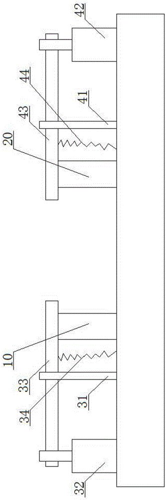
[0017] see figure 1 , as shown in the legend therein, a lever type clamping jig includes a first support block 10, a second support block 20, a first clamping assembly and a second clamping assembly, the first support block 10 and the second The support block 20 is arranged left and right, and the above-mentioned first clamping assembly includes a first support 31, a first driving device 32 and a first clamping plate 33, and the first support 21 and the first driving device 32 are sequentially arranged on the first support block. 10, the first clamping plate 33 is rotatably set with the first support 31 as a fulcrum, the left end of the first clamping plate 33 is hingedly connected with the driving end of the first driving device 32, and the first clamping plate 33 Rotate the right end of the first support block 10 to the upper set position or rotate to the left set position of the first support block 10, the second clamping assembly includes the second support 41, the second ...

Embodiment 2

[0027] The rest are the same as in Embodiment 1, except that the bottom of the right end of the horizontal plate of the above-mentioned first clamping plate is provided with several first grooves uniformly distributed, and the bottom of the left end of the horizontal plate of the above-mentioned second clamping plate is provided with There are several second grooves evenly distributed, and the grooves of the first groove and the second groove are triangular grooves.


PUM


Abstract

The invention discloses a lever type clamping jig. The lever type clamping jig comprises a first supporting block, a first clamping assembly, a second supporting block and a second clamping assembly. The first supporting block is arranged on the left side, and the second supporting block is arranged on the right side. The first clamping assembly comprises a first support, a first drive device and a first clamping plate. The first clamping plate is rotationally arranged with the first support as the pivot. The left end of the first clamping plate is connected with the drive end of the first drive device in a hinged manner. The second clamping assembly comprises a second support, a second drive device and a second clamping plate. The second clamping plate is rotationally arranged with the second support as the pivot. The right end of the second clamping plate is connected with the drive end of the second drive device in a hinged manner. According to the lever type clamping jig and the lever principle, the other ends of the clamping plates are downwards pressed by ejecting one ends of the clamping plates, and therefore locking or unlocking of the clamping plates is very convenient; and the parts, at the drive ends, of the clamping plates are arranged to be longer, and therefore the purpose of saving labor can be achieved.

Description

technical field [0001] The invention relates to the field of machining, in particular to a product clamping jig. Background technique [0002] When processing a product, it is necessary to clamp the product through a clamping fixture. The existing clamping fixture generally includes a cylinder and a rotatable clamping plate driven by the cylinder. Since the rotation of the clamping plate does not depend on the drive The device is driven, therefore, during the clamping process, an accident that the clamping plate rotates is very likely to occur, resulting in a safety accident. Contents of the invention [0003] In order to solve the above technical problems, the object of the present invention is to provide a lever-type clamping fixture. When the clamping plate clamps the product, the purpose of labor saving is realized through the principle of leverage, and since the clamping plate does not need to rotate, the clamping There is no accident of accidental rotation of the pl...

Claims


Application Information

Patent Timeline
Patent Type & Authority Applications(China)
IPC IPC(8): B25B11/00
CPCB25B11/00
Inventor 薛桂芬陆佳俊陆雪松
Owner SUZHOU JUNFA PRECISION MACHINERY
Why Eureka
Try Eureka