An auxiliary device for injection molding holes

An auxiliary device and injection molding technology, which is applied in the field of machining and manufacturing to achieve the effect of convenient cleaning and material saving

Active Publication Date: 2018-08-03
WUHU HENGXIN AUTO INTERIOR TRIM COMPANY
View PDF4 Cites 0 Cited by
  • Summary
  • Abstract
  • Description
  • Claims
  • Application Information

AI Technical Summary

Problems solved by technology

[0005] The purpose of the present invention is to overcome the need to remake the mold in the prior art to realize the switching between the hole processing and the non-hole processing of the injection molding product structure. In order to solve the shortage of forming holes, an auxiliary device for injection molding holes is provided. Using the technical solution of the present invention, the rapid switching between non-hole processing and hole processing can be realized by adjusting the extension and extension of the piston rod, without the need for injection molding. The injection mold can be remade in different states of the product to save costs, and the auxiliary device of the injection molding hole runs smoothly and accurately, which can prolong its service life and improve product quality; at the same time, the installation positions of these power output mechanisms are different due to the force translation. Affected by space, the molding of holes at specific positions on injection molded products is not affected by distance

Method used


Image

  • An auxiliary device for injection molding holes
  • An auxiliary device for injection molding holes
  • An auxiliary device for injection molding holes

Examples


Embodiment 1

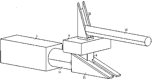
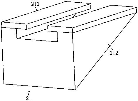
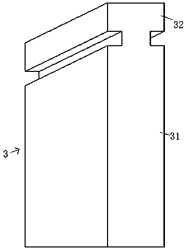
[0035] combine figure 1 , figure 2 , image 3 and Figure 4 , an auxiliary device for injection molding holes in this embodiment, such as figure 1 As shown, it includes the oil cylinder 1, the oil cylinder 1 includes the first piston rod 11, the auxiliary device of the injection molding hole also includes the oblique chute I21, the oblique chute II22, the linkage adapter block 3, the guide block 4 and the second Piston rod 12, wherein, the end of the first piston rod 11 is provided with an oblique chute I21, and the oblique chute I21 and oblique chute II22 are connected through the linkage adapter block 3, and the linkage adapter block 3 is covered with a guide block 4. The guide block 4 is installed on the injection mold, and the second piston rod 12 is arranged on the inclined chute II 22 .

[0036] In this embodiment, the materials of inclined chute I21, inclined chute II22, linkage adapter block 3 and second piston rod 12 are all 400c steel. The wear resistance requi...

Embodiment 2

[0048]An auxiliary device for injection molding holes in this embodiment, its basic structure is the same as that of Embodiment 1, the difference is that in this embodiment, the inclination angles of the inclined chute I21 and the inclined chute II22 are both 20°, and the inclination The number of the position chute I21 and the inclined position chute II22 are both two, and the number of linkage adapter blocks 3 is three.

Embodiment 3

[0050] An auxiliary device for injection molding holes in this embodiment, its basic structure is the same as that of Embodiment 1, the difference is that in this embodiment, the inclination angles of the inclined chute I21 and the inclined chute II22 are both 30°, and the inclination The number of the position chute I 21 and the inclined position chute II 22 are both three, and the number of linkage adapter blocks 3 is five.


PUM


Abstract

The invention discloses an auxiliary device for injection molding type holes, and belongs to the field of machining and manufacturing. The auxiliary device comprises an oil cylinder comprising a first piston rod, an inclined sliding groove I, an inclined sliding groove II, a linkage connection block, a guide block and a second piston rod wherein the inclined sliding groove I is formed in the tail end of the first piston rod and is connected to the inclined sliding groove II through the linkage connection block, the linkage connection block is provided with the guide block in a sleeved mode, and the inclined sliding groove II is provided with the second piston rod. The auxiliary device is mainly used for fast switching imporous machining and porous machining by adjusting extending-in and extending-out of the piston rods, there is no need to remanufacture injection molds, the production cost is low, and the operation is stable and accurate. Meanwhile, the installation positions of power output mechanisms are not influenced by space, and forming of holes in specific positions on injection products is not influenced by distance.

Description

technical field [0001] The invention relates to the technical field of mechanical processing and manufacturing, and more specifically relates to an auxiliary device for injection molding holes. Background technique [0002] At present, the injection molding products in the prior art are processed and formed by injection molds. In order to cooperate with the use of other products, the holes on the injection molding products have different functions, so that the injection molding products have various states, and the injection molding products are required to have holes or no holes somewhere. There are many states of holes, so as the position of the holes on the injection molding product changes, the original injection mold is limited by its own structure and cannot meet the production needs of the existing injection molding products. However, in order to save costs and avoid reprocessing the injection mold, Usually, during the injection molding manufacturing process of inject...

Claims


Application Information

Patent Timeline
Patent Type & Authority Patents(China)
IPC IPC(8): B29C45/17
CPCB29C45/17
Inventor 周超群王冬孟祥磊
Owner WUHU HENGXIN AUTO INTERIOR TRIM COMPANY
Why Eureka
Try Eureka