
Flexible wing flutter model variable in trailing edge

A flutter model and flexible wing technology, applied in the direction of wings, aircraft parts, ground devices, etc., can solve the problems of design and processing difficulties, the overall deflection of the rear edge frame of the wing, and the influence of the aerodynamic layout of the wing. Achieve high pressure and impact, simple geometry, easy processing

Active Publication Date: 2016-10-12
XIAN AIRCRAFT DESIGN INST OF AVIATION IND OF CHINA
View PDF4 Cites 10 Cited by
  • Summary
  • Abstract
  • Description
  • Claims
  • Application Information

AI Technical Summary

Problems solved by technology

[0003] The trailing edge frame section of the existing wing flutter model is usually designed as a whole, and the driving mechanism fixed on the leading edge of the wing drives the trailing edge frame section to deflect. The deflection is not conducive to the unsteady aerodynamic force distribution of the wing, which in turn makes the energy efficiency of the wing dissipated outward low. If the deflection of the trailing edge frame is to be carried out in stages, it is often necessary to design multiple drive mechanisms. The aerodynamic layout will have a greater impact and bring difficulties to design and processing

Method used


Image

  • Flexible wing flutter model variable in trailing edge
  • Flexible wing flutter model variable in trailing edge
  • Flexible wing flutter model variable in trailing edge

Examples


Embodiment Construction

[0033] In order to make the objectives, technical solutions and advantages of the present invention clearer, the technical solutions in the embodiments of the present invention will be described in more detail below in conjunction with the drawings in the embodiments of the present invention. In the drawings, the same or similar reference numerals denote the same or similar elements or elements having the same or similar functions throughout. The described embodiments are some, but not all, embodiments of the invention. The embodiments described below by referring to the figures are exemplary and are intended to explain the present invention and should not be construed as limiting the present invention. Based on the embodiments of the present invention, all other embodiments obtained by persons of ordinary skill in the art without creative efforts fall within the protection scope of the present invention. Embodiments of the present invention will be described in detail below ...


PUM


Abstract

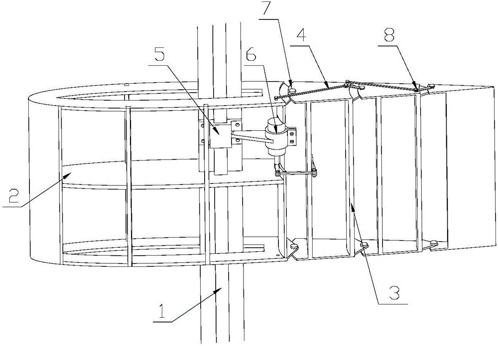
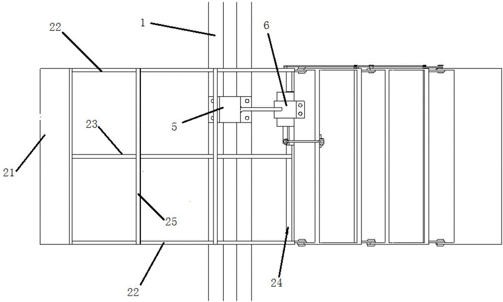
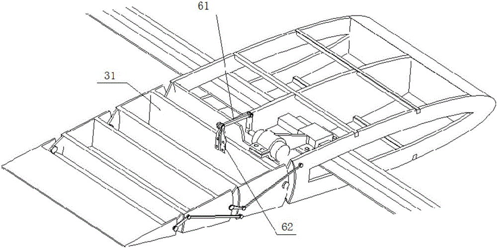
The invention relates to a flexible wing flutter model variable in trailing edge and belongs to the technical field of aeroelasticity tests. The flexible wing flutter model comprises a wing beam, a leading edge dimensional-shape frame section, a trailing edge frame section, a trailing edge control connection rod and a steering engine. The leading edge dimensional-shape frame section is fixed to the wing beam and hinged to the trailing edge frame section, the steering engine is arranged on the wing beam, and accordingly the trailing edge frame section can be driven to deflect relative to the leading edge dimensional-shape frame section through the steering engine; and one end of the trailing edge control connection rod is arranged on the leading edge dimensional-shape frame section, and the other end of the trailing edge control connection rod is arranged on the trailing edge frame section so that the deflection directions of multiple frame section bodies of the trailing edge frame section can be controlled. According to the flexible wing flutter model variable in trailing edge, a hinge rod mode is adopted, the wing trailing edge can be deformed through movement of the connection rod, wing unsteady aerodynamic distribution is changed so that a wing can dissipate energy outwards, and accordingly the flutter inhibition purpose is achieved.

Description

technical field [0001] The invention belongs to the technical field of aeroelasticity test, in particular to a flexible wing flutter model with variable trailing edge. Background technique [0002] Compared with the traditional wing structure, the active flexible wing structure can achieve real-time changes in important parameters such as wing shape, thickness, and camber, so on the one hand, it can reduce or even cancel the traditional wing active surface and related control systems. Change the distribution of unsteady aerodynamic forces on the wing, so that the wing can dissipate energy outward, so as to achieve the purpose of increasing the flutter speed and slowing down the gust and maneuvering load. [0003] The trailing edge frame section of the existing wing flutter model is usually designed as a whole, and the driving mechanism fixed on the leading edge of the wing drives the trailing edge frame section to deflect. The deflection is not conducive to the unsteady aer...

Claims


Application Information

Patent Timeline
Patent Type & Authority Applications(China)
IPC IPC(8): B64C3/28B64F5/00
CPCB64C3/28B64F5/00
Inventor 陈海黄国宁张红波党云卿郭润江
Owner XIAN AIRCRAFT DESIGN INST OF AVIATION IND OF CHINA
Learn More