An industrial circulating water online oil monitoring and degreasing device

An industrial circulating water and oily technology, which is applied in the direction of grease/oily substance/floating matter removal device, general water supply saving, centrifugal separation water/sewage treatment, etc., can solve the problem of unstable fluid form, unstable and fluctuating oil content, increasing The difficulty of separation and dehydration again

Active Publication Date: 2022-06-07
SHANGHAI SOARUP ENERGY TECH
View PDF9 Cites 0 Cited by
  • Summary
  • Abstract
  • Description
  • Claims
  • Application Information

AI Technical Summary

Problems solved by technology

[0012] 1) In the case of low flow rate, the shape of the fluid entering the cyclone separation equipment is unstable. In the center of the cylinder section and the cone section, the swirl flow is not enough to make the dirty oil form an oil core, or it is difficult to form a stable fluid in the center of the swirl flow. The oil core, the dirty oil is easy to re-enter the rotating water flow, and the phenomenon of drainage and mixed oil will appear, which will weaken the separation effect
[0013] 2) Under variable working conditions, the oil content that continues to enter the cyclone separation equipment fluctuates unsteadily, the fluid flow form in the cyclone separation equipment is unstable, and the shape of the oil core in the center of the cyclone fluctuates, resulting in oily drainage. Phenomenon
[0014] 3) In order to ensure the degreasing effect of the single cyclone separation equipment, the water content of the sewage oil is large, and it is necessary to further remove a large amount of water contained in the sewage oil; if it is processed after long-distance transportation, it will also cause deepening of the oil-water mixing emulsification during the transportation process, increasing Difficulty of re-separation and dehydration

Method used


Image

  • An industrial circulating water online oil monitoring and degreasing device
  • An industrial circulating water online oil monitoring and degreasing device
  • An industrial circulating water online oil monitoring and degreasing device

Examples


Embodiment Construction

[0035] The present invention is further described below with reference to the accompanying drawings, and embodiments of the present invention are given.

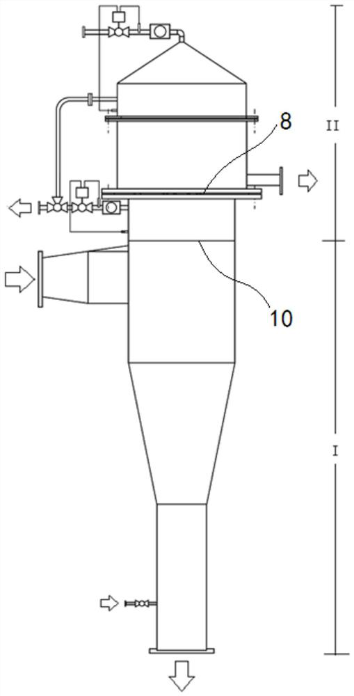
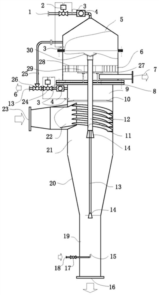
[0036] This industrial circulating water on-line oil monitoring and degreasing device consists of an inverted bottle-shaped cavity at the bottom and an upper part of the inverted bottle-shaped cavity, which is connected to the inverted bottle-shaped cavity through a partition plate 8. The isolated conical frustum-shaped cavity is connected and assembled. The inverted bottle-shaped cavity below the plate 10 is divided into a hydrocyclone separation unit I, and the above part of the annular perforated arch baffle 10 and the entire frustum-shaped cavity part form a sewage oil sedimentation separation and collection unit II;

[0037] The described hydrocyclone separation unit 1 consists of a rapid separation cavity 21, a conical separation cavity 20 in the middle and a deep separation cavity 19 in the tail, which are sequentiall...


PUM


Abstract

An on-line oil monitoring and degreasing device for industrial circulating water, which is composed of an inverted bottle-shaped cavity at the bottom and a frustum-shaped cavity arranged on the upper part of the inverted bottle-shaped cavity and separated by a separation plate formed; the upper cavity of the inverted bottle-shaped cavity is separated into a hydrocyclone separation unit by passing through an annular perforated arched baffle, and the inverted bottle-shaped cavity below the annular perforated arched baffle, The above part of the ring-shaped perforated arch baffle and the entire frustum-shaped cavity form a dirty oil sedimentation and separation collection unit; the hydrocyclone separation unit is composed of the upper quick separation chamber, the middle conical separation chamber and the Tail depth separation chamber; the upper part of the sewage oil sedimentation separation collection unit is a truncated cone-shaped combined chamber, and the lower part is a pre-isolation composed of an annular arched baffle with holes in the upper chamber of the inverted bottle-shaped chamber as the bottom plate. At the same time, the outer cavity of the pre-isolated dirty oil recovery room is provided with a dirty oil discharge mechanism with a monitoring function.

Description

technical field [0001] The invention relates to a fluid cyclone separation technology, in particular to an on-line oil monitoring and oil removal device for industrial circulating water, which is especially suitable for removing light and heavy oil mixed into circulating water when the industrial circulating water is polluted by an oily medium. The components are separated from the circulating water body to eliminate the oily pollution in the circulating water system and recover the oily pollution. Background technique [0002] A simple-structured fluid material separation device used in cyclone separation, usually consisting of a feed port, a cyclone cylinder section, a cyclone cone section, a light component overflow port, a heavy component discharge port, and accessories . The separation principle is centrifugal sedimentation and centripetal floating. The heterogeneous mixed fluid to be separated is forced to make a rotary motion after entering the cyclone separator at ...

Claims


Application Information

Patent Timeline
Patent Type & Authority Patents(China)
IPC IPC(8): C02F1/40C02F1/38
CPCC02F1/38C02F1/40C02F2001/007Y02A20/204
Inventor 袁黎明
Owner SHANGHAI SOARUP ENERGY TECH
Why Eureka
Try Eureka