Warp tension detection mechanism

A tension detection and warp yarn technology, which is applied in tension measurement, looms, textiles, etc., can solve problems such as insufficient beating force, failure to reach the designed density, and jumping of the back beam, so as to achieve flexible use, improve accuracy, and prevent the back beam beating effect

Inactive Publication Date: 2016-10-12
WUJIANG JINYE WEAVING
View PDF3 Cites 1 Cited by
  • Summary
  • Abstract
  • Description
  • Claims
  • Application Information

AI Technical Summary

Problems solved by technology

[0002] The traditional warp tension detection mechanism uses the proximity switch to judge the position of the backrest, and indirectly detects the warp tension. It will cause the back beam to jump, resulting in insufficient beating force, not only failing to reach the designed density, but also affecting the accuracy of warp tension adjustment

Method used


Image

  • Warp tension detection mechanism

Examples


Embodiment Construction

[0014] The technical solution of the present invention will be further described in detail below in conjunction with the accompanying drawings and specific embodiments, so that those skilled in the art can better understand the present invention and implement it, but the examples given are not intended to limit the present invention.

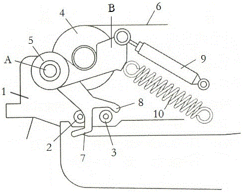
[0015] Such as figure 1 As shown, a warp tension detection mechanism includes a frame 1 and a back beam 4 arranged on the frame 1, the back beam 4 is provided with a swing rod 5, and the swing rod 5 includes an A end and a B end, and also includes a damping One end of the damper 9 is arranged on the frame 1 and the other end is arranged on the B end of the swing rod 5 in a detachable manner, and one end of the tension spring 10 is arranged on the frame 1 and the other end is arranged on the swing rod 5, the frame 1 is also provided with a first proximity switch 2 and a second proximity switch 3, and the end A of the swing rod 5 is provided with ...


PUM


Abstract

The invention discloses a warp tension detection mechanism. The warp tension detection mechanism comprises a rack and a rear beam arranged on the rack, the rear beam is provided with a swing rod, and the swing rod comprises an end A and an end B. The warp tension detection mechanism is characterized by further comprising a damper; one end of the damper is arranged on the rack, the other end of the damper is debatably arranged at the end B of the swing rod, one end of a tension spring is arranged on the rack, the other end of the tension spring is arranged at the end B of the swing rod, a first proximity switch and a second proximity switch are further arranged on the rack, a first detection body and a second detection body are arranged at the end A of the swing rod, the first detection body can induct the first proximity switch and the second proximity switch, and the second detection body can induct the second proximity switch. The warp tension detection mechanism is more flexible to use and capable of improving the accuracy of warp tension adjustment.

Description

technical field [0001] The invention relates to a warp tension detection mechanism. Background technique [0002] The traditional warp tension detection mechanism uses the proximity switch to judge the position of the backrest, and indirectly detects the warp tension. It will cause the back beam to jump, resulting in insufficient beating force, not only failing to reach the designed density, but also affecting the accuracy of warp tension adjustment. Contents of the invention [0003] In view of the above problems, the present invention provides a warp tension detection mechanism, which is more flexible in use and improves the accuracy of warp tension adjustment. [0004] In order to achieve the above-mentioned technical purpose and achieve the above-mentioned technical effect, the present invention is realized through the following technical solutions: [0005] A warp tension detection mechanism, comprising a frame and a rear beam arranged on the frame, the rear beam is...

Claims


Application Information

Patent Timeline
Patent Type & Authority Applications(China)
IPC IPC(8): D03D49/12G01L5/04
CPCD03D49/12G01L5/04
Inventor 蒋雪明
Owner WUJIANG JINYE WEAVING
Why Eureka
Try Eureka