End position style grinding roller grinder

A technology of grinding rollers and mills, applied in grain processing, etc., can solve the problems of affecting the grinding effect, unstable operation, and upward jumping of the grinding cylinder, and achieve the effect of fineness, stable operation, and increased rotation speed of the grinding cylinder

Inactive Publication Date: 2009-10-21
郝志刚
View PDF5 Cites 0 Cited by
  • Summary
  • Abstract
  • Description
  • Claims
  • Application Information

AI Technical Summary

Problems solved by technology

The disadvantage of this milling is that the grinding cylinder is only provided with a grinding cylinder support seat at the lower part of the grinding cylinder to support the grinding cylinder in one direction, so the grinding cylinder is prone to jump upward during the operation, causing unstable operation and affecting the grinding effect

Method used


Image

  • End position style grinding roller grinder
  • End position style grinding roller grinder
  • End position style grinding roller grinder

Examples


Embodiment 1

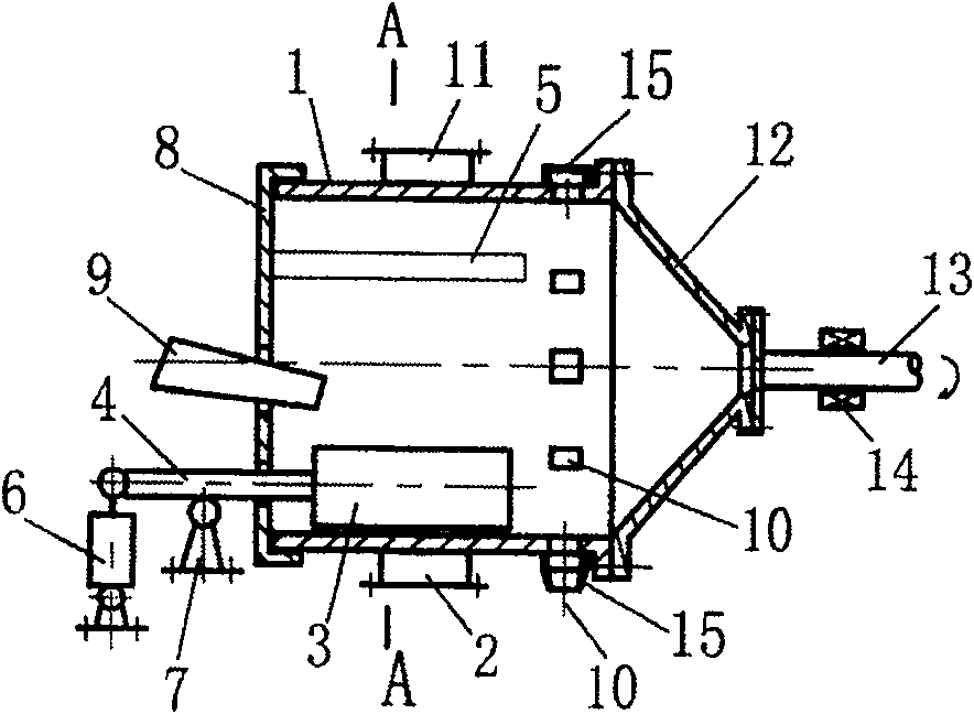
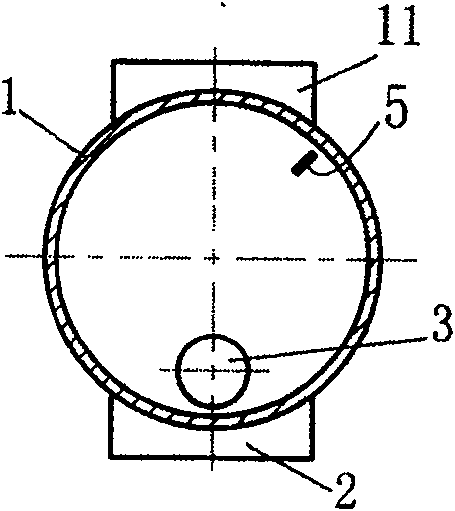
[0019] Example 1, see figure 1 , figure 2 .

[0020] It includes a grinding cylinder 1, and the lower part of the grinding cylinder 1 is provided with a grinding cylinder supporting seat 2. The grinding cylinder supporting seat 2 can be a sliding bearing structure, or a supporting wheel structure with multi-point support in the circumferential direction, or a rolling bearing structure, and At least one group is arranged along the axial direction of the grinding cylinder 1, and the figure shows the schematic structure of the sliding bearing; one end of the grinding cylinder 1 has an end cover 8, and the grinding cylinder 1 is equipped with a grinding roller 3, a roller shaft 4, a scraper and a material guide The device 5, the scraper and the material guide device can be combined into one. The illustrated part 5 is a schematic diagram of the combination of the scraper and the material guide device. The scraper and the material guide device 5 can also be independently produced....

Embodiment 2

[0024] Example 2, see Figure 4 .

[0025] Figure 4 It is a modified implementation structure of the present invention, which provides another structural form of the discharge port 10 .

[0026] Figure 4 Among them, the outer section of the ring member 12 is a cylindrical section structure 16, and is provided with a screw discharge device 17 placed in the ring member 12, the inner end of the screw discharge device has a material inlet 18, and the screw discharge device The outer section of the device is located in the cylindrical section structure 16 of the outer section of the ring member 12, and is joined and connected with the inner wall of the cylindrical section structure 16. The discharge port 10 is located between the screw discharge device 17 and the cylindrical section structure 16. On the cylinder wall of the joint part, and several are arranged along the circumference of the cylinder wall. There is also a deflector 19 in the grinding cylinder 1 that allows the ...

Embodiment 3

[0028] Example 3, see Figure 5 , Image 6 .

[0029] This example structure is based on embodiment 1 or embodiment 2, Figure 5 Represented is based on the structure of embodiment 1, on the inner section of the roller shaft 4, a grinding roller frame 21 is set, and the grinding roller frame 21 is provided with two described grinding rollers 3, and the grinding roller frame 21 can also be Three or more grinding rollers 3 are arranged, that is, at least two of the grinding rollers 3 are arranged on the grinding roller frame 21, and the scraper and the material guide device 5 are arranged between the adjacent two grinding rollers. A grinding roller 3 can form a plurality of running-in surfaces with the inner wall of the grinding cylinder 1, which is beneficial to improve production efficiency; the transmission shaft 13 is provided with a circumferential support 14, and a second circumferential support 14 as described in Example 2 can also be provided at the same time. Support...


PUM


Abstract

End mounted roller mill. The lower part of the grinding cylinder (1) has a grinding cylinder support seat (2), one end of the grinding cylinder has an end cover (8), and the grinding cylinder has a grinding roller (3), a roller shaft (4) and a scraper and a material guide device (5 ), the inner end of the roller shaft is connected to one end of the grinding roller, and the outer end of the roller shaft extends out of the end cover (8) on the end side, and there is a pressure device (6) and a roller shaft support (7) on it, There is a feeding device (9) and a discharge port (10), the upper part of the grinding cylinder (1) has a grinding cylinder support (11), the other end of the grinding cylinder is connected to the ring (12), and the outer end of the ring (12) is connected to the transmission The shaft (13), the transmission shaft is provided with a circumferential bearing (14). The grinding cylinder support (11), the grinding cylinder support seat (2) and the circumferential support (14) on the transmission shaft work together to support and restrain the grinding cylinder in the circumferential direction, which can effectively prevent the grinding cylinder from beating and reduce The vibration generated by the beating makes the grinding cylinder run stably and improves the grinding effect.

Description

technical field [0001] The invention relates to a material grinding equipment, in particular to an end-mounted roller mill. Background technique [0002] The patent specification with the application number "03235660.8" and the announcement number "2675258" announced on February 2, 2005 discloses a grinding wheel with an end position. The grinding includes a grinding cylinder, and the lower part of the grinding cylinder is provided with a grinding cylinder support There are grinding rollers, roller shafts, scrapers and material guide devices in the grinding cylinder, one end of the roller shaft is connected to one end of the grinding roller, and the other end of the roller shaft extends out of the grinding cylinder, and a pressure device and Roller shaft support, that is, the positioning of the grinding roller is achieved through the connection of the roller shaft at one end. The feeding end of the grinding cylinder has a feeding device, and the discharging end of the grindi...

Claims


Application Information

Patent Timeline
Patent Type & Authority Patents(China)
IPC IPC(8): B02C15/16
Inventor 郝志刚
Owner 郝志刚
Why Eureka
Try Eureka