Pay-off pulley device

A pay-off pulley and cable technology, applied in transportation and packaging, thin material handling, cable laying equipment, etc., can solve the problems of low work efficiency, increased workload, inability to adjust, etc., to achieve flexible use, avoid pairing work, Protection from wear and tear

Pending Publication Date: 2022-08-09
国网河南省电力公司新安县供电公司 +1
View PDF0 Cites 0 Cited by
  • Summary
  • Abstract
  • Description
  • Claims
  • Application Information

AI Technical Summary

Problems solved by technology

The usual pay-off pulley is erected on the cross arm, and the groove of the pulley is fixed in shape and cannot be adjusted. One pulley groove corresponds to one type of thick and thin cable. As a result, it is necessary to equip multiple pay-off pulley
Sometimes, because the pulleys carried by the staff do not correspond to the cables, they must return to the warehouse to find matching pulleys, which increases unnecessary workload and reduces work efficiency.

Method used


Image

  • Pay-off pulley device
  • Pay-off pulley device
  • Pay-off pulley device

Examples


Embodiment 1

[0027] Example 1: see Figure 1-4 ;

[0028] The present invention provides the following technical solutions:

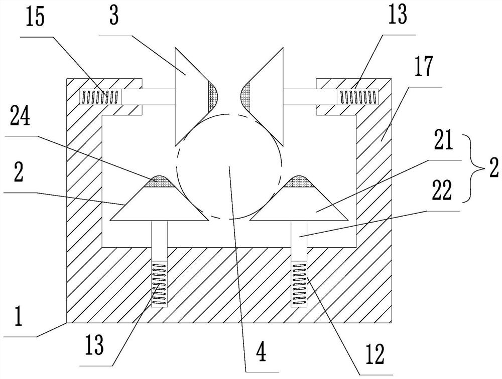
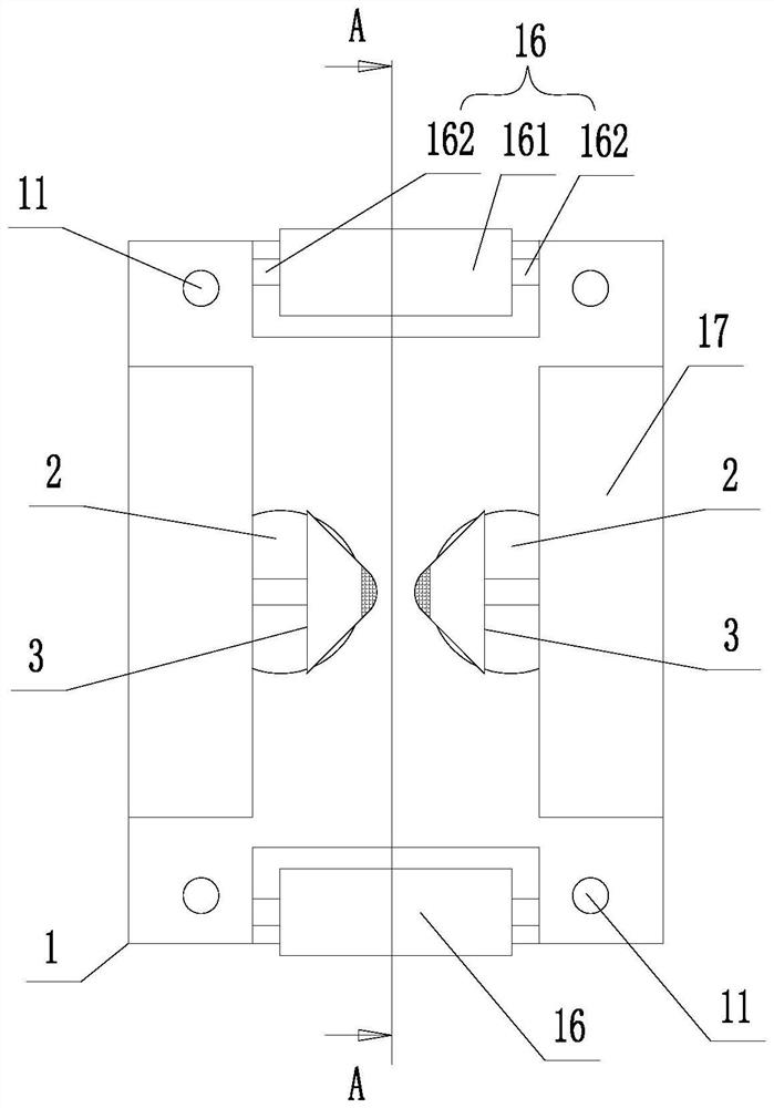
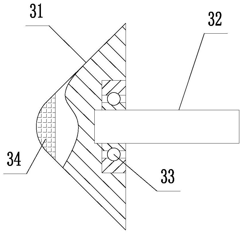
[0029] A pay-off pulley device, including a base 1, the upper surface of the base 1 is provided with two left-right symmetrical vertical plate parts 17 and a plurality of through holes 11 for mounting the base 1 on a support, so that the bolts can pass through the base 1. It is installed on the cross arm through the through hole 11; the upper surface of the base 1 is also provided with a pair of vertical first sockets 12, and the upper end of the vertical plate portion 17 is provided with a horizontal second socket 13, so The first insertion hole 12 and the second insertion hole 13 are respectively provided with a first spring 14 and a second spring 15; the front and rear edges of the upper surface of the base 1 are provided with rotatable roller shafts 16. The shaft 16 is used to reduce the wear when the cable passes through the front and rear edges of the upper ...

Embodiment 2

[0039] Example 2: see Figure 1-5 ;

[0040] A pay-off pulley device is different from Embodiment 1 in that the base 1 has four first sockets 12, and each of the first sockets 12 is plugged with one of the first rotating cone heads 2 ;

[0041] The four first jacks 12 are divided into two groups, and each group of two first jacks 12 is located on the left and right sides of the cable respectively; the two groups of first jacks 12 are along the axial direction of the cable. Arrangement; the second rotating cone head 3 is located in the middle of the two groups of first sockets 12; such as Figure 5 shown.

[0042] Correspondingly, there are also four first rotating cone heads 2 . Compared with Embodiment 1, this embodiment has the advantages of Embodiment 1. The number of the first rotating cone heads 2 in the lower part is more, the lifting capacity of the cable is stronger, and it can bear a larger traction force, so that the When pulling the cable through the device, it...


PUM


Abstract

The invention discloses a paying-off pulley device which comprises a base, and the upper surface of the base is provided with two vertical plate parts in bilateral symmetry and a plurality of through holes used for installing the base on a supporting object. First rotary conical heads are inserted into first insertion holes preset in the upper surface of the base, the number of the first insertion holes is at least two, a first conical part of each first rotary conical head can rotate, and the small conical end of each first rotary conical head faces upwards; second rotary conical heads are inserted into second insertion holes preset in the upper ends of the two vertical plate parts correspondingly. The second conical parts of the two second rotary conical heads can rotate, and the small conical ends of the second rotary conical heads are horizontally opposite. A first spring and a second spring are preset in the first jack and the second jack respectively, and the first spring and the second spring are used for driving the first conical part and the second conical part to radially clamp the lower side and the upper side of a cable to be erected respectively. According to the invention, workers can automatically adapt to cables with different thicknesses, and the use is convenient.

Description

technical field [0001] The invention belongs to the technical field of power transmission line construction or maintenance, in particular to a pay-off pulley device. Background technique [0002] The pay-off pulley is usually used for laying or erecting cable conductors, and it is installed on the cross arm of the transmission tower to change the direction of the cable and protect the cable from friction caused by the change of the extension direction. Usually, the pay-off pulley is erected on the cross arm. The groove of the pulley is a fixed shape and cannot be adjusted. One kind of pulley groove corresponds to one kind of thickness of cable, which leads to the need to equip various kinds of cables during pay-off construction or maintenance and replacement of cables. Pay-off pulley. Sometimes because the pulleys carried by the staff do not correspond to the cables, they must return to the warehouse to find the matching pulleys, which increases the unnecessary workload and...

Claims


Application Information

Patent Timeline
Patent Type & Authority Applications(China)
IPC IPC(8): B65H57/14B65H49/00H02G1/06
CPCB65H57/14B65H49/00H02G1/06B65H2404/1312B65H2404/14B65H2404/27B65H2701/34
Inventor 贾明辉侯改伟赵亚伟唐东杰付潭樊毅孟东杰
Owner 国网河南省电力公司新安县供电公司
Why Eureka
Try Eureka