Prefabricated supporting steel frame column end splicing node structure

A technology of joint structure and steel frame, applied in the direction of building structure, construction, etc., can solve problems such as affecting the connection between supporting steel frame and surrounding beams, splicing joint form can not meet the requirements, not suitable for the development needs of industrialized buildings, etc., to meet the prefabrication requirements Assembly and installation requirements, meeting the bearing performance requirements of multi-storey buildings, and the effect of easy assembly and disassembly

Active Publication Date: 2018-04-13
TONGJI UNIV
View PDF8 Cites 0 Cited by
  • Summary
  • Abstract
  • Description
  • Claims
  • Application Information

AI Technical Summary

Problems solved by technology

Among them, welded joints save more materials under the premise of ensuring safety, but the on-site construction workload is large, which does not meet the development needs of industrialized buildings; the connection of spliced ​​plates will affect the connection between the supporting steel frame and the surrounding beams; The internal force is relatively large, and only the existing end plate connection cannot meet the bearing capacity requirements
Therefore, the existing splicing node form cannot meet the requirements

Method used


Image

  • Prefabricated supporting steel frame column end splicing node structure
  • Prefabricated supporting steel frame column end splicing node structure
  • Prefabricated supporting steel frame column end splicing node structure

Examples


Embodiment 1

[0034] The implementation of the present invention will be illustrated by specific specific examples below, and those skilled in the art can easily understand other advantages and effects of the present invention from the contents disclosed in this specification.

[0035] A prefabricated supporting steel frame column end splicing node structure, its structure is characterized by:

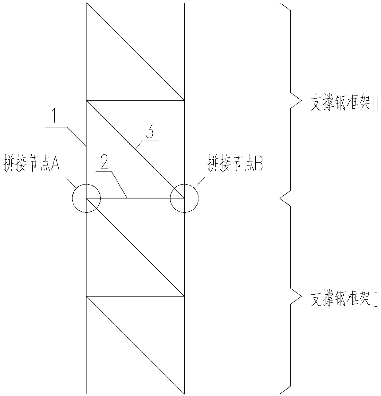
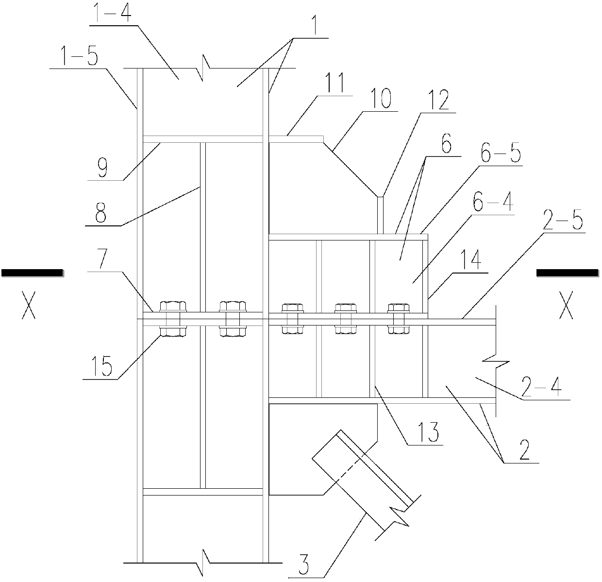
[0036] The column end splicing joint structure of the prefabricated supporting steel frame (referred to as the node) is located between two prefabricated supporting steel frames (referred to as the supporting steel frame), such as figure 1 As shown, the supporting steel frame I is located at the lower part of the node, and the supporting steel frame II is located at the upper part of the node. Such as figure 1 As shown, the supporting steel frame is composed of H-shaped columns 1, H-shaped beams 2 and supports 3,

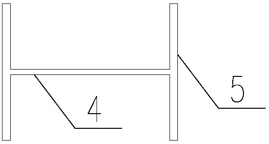
[0037] As we all know, any H-shaped column and H-shaped beam in the art are compose...


PUM


Abstract

The present invention provides an assembled support steel frame column end splicing node structure, the assembled support steel frame column end splicing node structure is located between two assembled support steel frames, the support steel frame I is located at the lower part of the node, and the support steel frame II is located at upper part of the node. The supporting steel frame consists of H-columns, H-beams and braces. The supporting steel frame I welds the end plate on the top of the H-shaped column, sets the stiffener at the joint between the H-shaped column and the H-shaped beam, welds the horizontal stiffener on the H-shaped column, and sets the horizontal stiffener between the H-shaped column end plate and the H-shaped column Vertical stiffeners, welded stiffeners on the H-shaped beam, and bolt holes on the upper flange of the H-shaped beam. The supporting steel frame II welds the end plate at the bottom of the H-shaped column, welds the H-shaped spliced ​​beam at the bottom of the H-shaped column, welds the stiffener on the H-shaped spliced ​​beam, opens bolt holes on the lower flange of the H-shaped spliced ​​beam, and splices the H-shaped column and the H-shaped Stiffeners are set at the beam joints, horizontal stiffeners are welded on the H-shaped columns, and vertical stiffeners are set between the end plates of the H-shaped columns and the horizontal stiffeners of the H-shaped columns.

Description

technical field [0001] The invention belongs to the technical field of steel structure construction of prefabricated buildings, in particular to a spliced ​​joint structure at the end of a supporting steel frame column Background technique [0002] The construction industry is an important material production sector of the national economy, and has a close relationship with the development of the entire country's economy and the improvement of people's lives. In recent years, with the continuous deepening of the reform of the construction industry, the construction industry has continued to develop rapidly, the material and technological foundation has been significantly enhanced, the demographic dividend has gradually disappeared, and the requirements for energy conservation and environmental protection have become higher and higher. The on-site construction production method based on low labor prices is becoming increasingly challenged. The prefabricated building has fast...

Claims


Application Information

Patent Timeline
Patent Type & Authority Patents(China)
IPC IPC(8): E04B1/19E04B1/58
CPCE04B1/19E04B1/1903
Inventor 李国强郭宏印陆烨
Owner TONGJI UNIV
Why Eureka
Try Eureka