
A bio-sensing window frame

A bio-sensing and window frame technology, which is applied in the direction of window/door frame, window/door, building structure, etc., can solve the problems of unstable working voltage and difficult to meet, so as to improve reliability, eliminate false alarms, and reduce defects interference effect

Active Publication Date: 2018-02-16
成都华立安安防科技有限公司
View PDF6 Cites 0 Cited by
  • Summary
  • Abstract
  • Description
  • Claims
  • Application Information

AI Technical Summary

Problems solved by technology

[0002] Compared with other anti-theft sensing devices, bio-sensing window frames are relatively rare in the current domestic and foreign markets. Compared with other anti-theft devices, such as infrared sensing and other devices, it has the physical characteristics of non-contact detection of human biomagnetic field to generate alarm signals, and is reliable. High, good security and other advantages, such as a kind of electronic anti-theft fence and its manufacturing method recorded in Chinese patent CN01107018, the electronic anti-theft fence disclosed in this patent is a kind of electronic anti-theft fence of bio-induction, but this bio-induction device is easily affected by Interference from the external environment, such as small animals, temperature, rainy weather and other environmental interference, makes the working voltage unstable and falsely triggers, causing an alarm. In addition, its installation is limited by the environment. For example, the induction coil and the induction electrode need to be installed with a bracket, which is difficult to meet Beautiful and convenient, it is suitable for the diversified use requirements of window frames, and its working parameters need to be manually adjusted, and the construction speed is limited. If manual adjustment of the working frequency and alarm voltage is required, it is difficult to meet the needs of stable and reliable indoor and outdoor environments and fast and convenient construction. Usage requirements

Method used


Image

  • A bio-sensing window frame
  • A bio-sensing window frame
  • A bio-sensing window frame

Examples


Embodiment Construction

[0045] The present invention will be further described in detail through the drawings and examples below. Through these descriptions, the features and advantages of the present invention will become more apparent.

[0046] The word "exemplary" is used exclusively herein to mean "serving as an example, embodiment, or illustration." Any embodiment described herein as "exemplary" is not necessarily to be construed as superior or better than other embodiments. While various aspects of the embodiments are shown in drawings, the drawings are not necessarily drawn to scale unless specifically indicated.

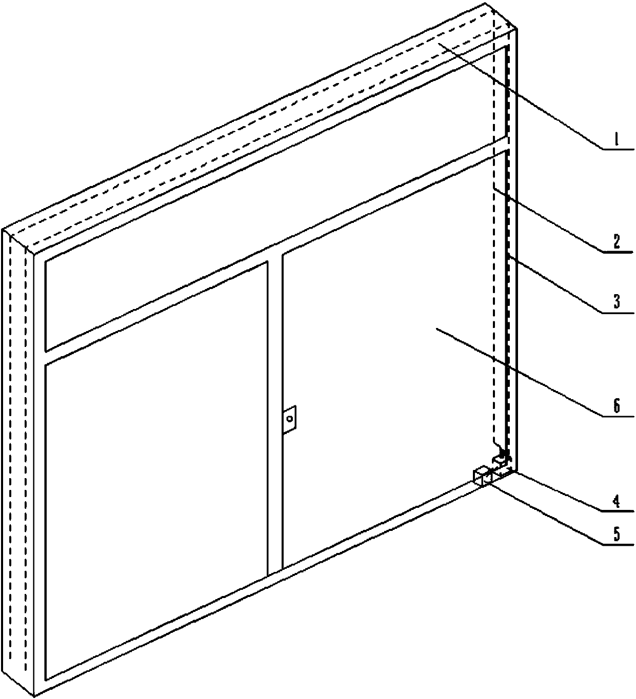
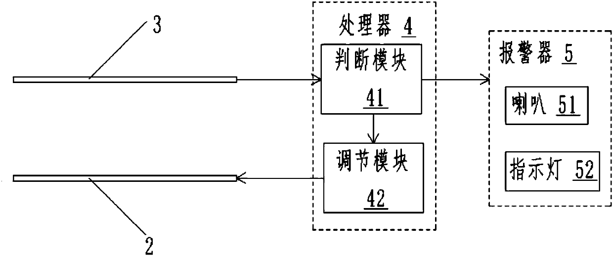
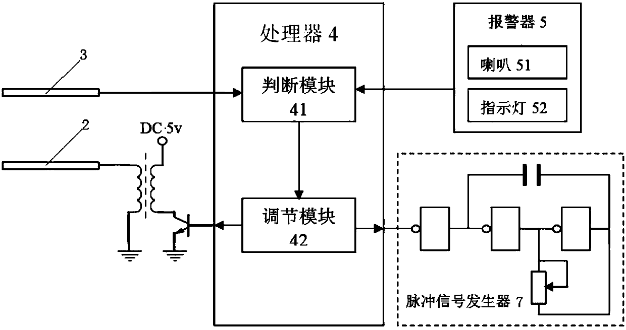
[0047] According to the bio-sensing window frame provided by the present invention, such as figure 1 and figure 2 As shown in , the window frame includes frame 1, excitation wire 2, induction wire 3, processor 4 and alarm 5, wherein, the frame 1 is rectangular or U-shaped, and the excitation wire 2, induction wire 3, processing Both the alarm 4 and the alarm 5 are preferably in...


PUM


Abstract

A biological sensing window frame, the window frame comprising a frame (1), an excitation wire (2), a sensing wire (3), a processor (4) and an alerter (5), wherein the excitation wire (2) is mounted on the frame (1) so as to form a sensing electric field; the sensing wire (3) is mounted on the frame (1) and is located in the sensing electric field so as to sense information about a sensing electric field change caused by a biological magnetic field and transmit the information to the processor (4); the processor (4) determines, according to the information, whether it is necessary to start an alerter; and the excitation wire (2) and the sensing wire (3) are arranged in parallel. The biological sensing window frame can self adjust a working parameter so as to fully adapt to the interference of an external environment, thereby increasing the application range and reliability of the biological sensing window frame.

Description

technical field [0001] The invention relates to the technical field of biological detection sensors, in particular to a biological sensing window frame. Background technique [0002] Compared with other anti-theft sensing devices, bio-sensing window frames are relatively rare in the current domestic and foreign markets. Compared with other anti-theft devices, such as infrared sensing and other devices, they have the physical characteristics of non-contact detection of human biomagnetic field to generate alarm signals, and are reliable. High, good security and other advantages, such as a kind of electronic anti-theft fence and its manufacturing method recorded in Chinese patent CN01107018, the electronic anti-theft fence disclosed in this patent is a kind of electronic anti-theft fence of bio-induction, but this bio-induction device is vulnerable to Interference from the external environment, such as small animals, temperature, rainy weather and other environmental interferen...

Claims


Application Information

Patent Timeline
Patent Type & Authority Patents(China)
IPC IPC(8): E06B1/36E06B7/28G08B13/24G01V3/10
CPCE06B1/36E06B7/28G01V3/088G01V3/105G08B13/2491G08B13/24
Inventor 孙建华
Owner 成都华立安安防科技有限公司
Learn More