UAV (unmanned aerial vehicle) built-in exhaust pipe

An exhaust pipe and unmanned aerial vehicle technology, applied in the field of exhaust pipes, can solve the problems of inconvenient transportation and moving operators, unclean wiping, etc., and achieve the effect of preventing direct ejection

Inactive Publication Date: 2016-10-12
南昌白龙马航空科技有限公司
View PDF0 Cites 0 Cited by
  • Summary
  • Abstract
  • Description
  • Claims
  • Application Information

AI Technical Summary

Problems solved by technology

The fuselage needs to be wiped after each operation, and the wiping is not clean, which brings a lot of inconvenience to the operators during transportation and moving

Method used


Image

  • UAV (unmanned aerial vehicle) built-in exhaust pipe

Examples


Embodiment 1

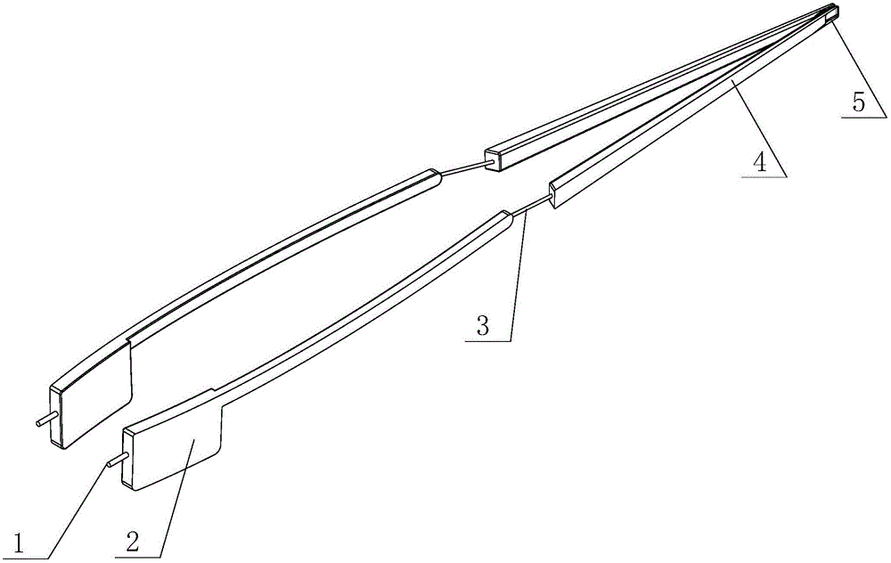
[0016] as attached figure 1 As shown, a built-in exhaust pipe for a UAV includes an air intake pipe 1 connected to the exhaust port of the UAV engine. The pipe rear pipe 4, the exhaust pipe front pipe 2 and the exhaust pipe rear pipe 4 are fixed on both sides inside the drone fuselage, and the end of the exhaust pipe rear pipe 4 stretches out of the drone fuselage tail.

[0017] The front portion of the exhaust pipe front pipe 2 in this embodiment is flat.

[0018] In order to cater to the internal shape of the fuselage, the front pipe 2 of the exhaust pipe is designed as an arc.

[0019] The end of the exhaust pipe rear pipe 3 is provided with an oil retaining fence 5 .


PUM


Abstract

The invention relates to an exhaust pipe, in particular to a built-in exhaust pipe for an unmanned aerial vehicle. Its structure includes the intake pipe connected to the exhaust port of the UAV engine. The rear end of the intake pipe is connected in series with the front pipe of the exhaust pipe, the transition pipe and the rear pipe of the exhaust pipe. The pipe rear pipe is fixed on both sides inside the drone fuselage, and the end of the exhaust pipe rear pipe stretches out of the drone fuselage tail. The built-in exhaust pipe of an unmanned aerial vehicle of the present invention can prevent the exhaust gas and waste oil discharged from the engine from floating on the fuselage.

Description

technical field [0001] The invention relates to an exhaust pipe, in particular to a built-in exhaust pipe for an unmanned aerial vehicle. Background technique [0002] Industrial-grade drones are developing rapidly in China and have become the leader in the drone industry. Industrial-grade oil-powered UAVs occupy an important position in industrial-grade UAVs. [0003] The engines of the current industrial oil-powered UAVs are generally installed on the nose, and the exhaust gas from the engine will flow to the fuselage along the airflow when the UAV is flying. Exhaust gas contains dirt such as carbon particles, unburned fuel and lubricating oil, which will stick to the outer surface of the fuselage, making the fuselage full of oil, and the smell of gasoline and exhaust gas will remain in the fuselage superior. The fuselage needs to be wiped after each operation, and the wiping is not clean, which brings a lot of inconvenience to the operators during transportation and mo...

Claims


Application Information

Patent Timeline
IPC IPC(8): F01N13/08B64D33/04
CPCF01N13/08B64D33/04F01N2590/00
Inventor 耿立威
Owner 南昌白龙马航空科技有限公司
Why Eureka
Try Eureka