Air conditioner, axial flow fan and stator blade of axial flow fan

A technology of axial flow fans and stationary blades, applied in axial flow pumps, air conditioning systems, machines/engines, etc., can solve the problems of reducing axial fluid flow, generating noise, reducing air flow velocity, etc., to reduce air volume loss, Effect of reducing kinetic energy loss and reducing airflow noise

Active Publication Date: 2016-10-12
WUHU MATY AIR CONDITIONING EQUIP CO LTD +1
View PDF8 Cites 8 Cited by
  • Summary
  • Abstract
  • Description
  • Claims
  • Application Information

AI Technical Summary

Problems solved by technology

However, it has been found through practice that when the axial fan is applied to the air-conditioning cabinet, if figure 1 As shown, the rotor blade is located on the B' side of the D' position, and the stationary vane is located on the A' side of the D' position, and the air flows from the B' side to the A' side, wherein, at the position P1', it corresponds to the axial flow At the trailing edge of the vane of the fan, there will be a large wake loss, which will not only reduce the airflow velocity but also generate noise. In addition, if figure 1 As shown, at the position P2', that is, at the downstream position corresponding to the trailing edge of the stator vane of the axial flow fan, the air flow will appear to be obviously deflected to the left. The design requirement of air outlet injection leads to insignificant or no wind feeling at a position far from the air supply outlet of the air conditioning cabinet, and for axial flow fans used in non-air conditioning cabinets such as air conditioning outdoor units and purifiers When the left-biased fluid collides with the air duct, it will cause noise problems, and a large amount of left-biased fluid will collide with the axial fluid to cause turbulent flow, which will easily increase the impact of noise, and will correspondingly reduce the flow rate of the axial fluid, resulting in air conditioning The air supply volume of the cabinet machine is reduced

Method used


Image

  • Air conditioner, axial flow fan and stator blade of axial flow fan
  • Air conditioner, axial flow fan and stator blade of axial flow fan
  • Air conditioner, axial flow fan and stator blade of axial flow fan

Examples


Embodiment Construction

[0062] In order to understand the above-mentioned purpose, features and advantages of the present invention more clearly, the present invention will be further described in detail below in conjunction with the accompanying drawings and specific embodiments. It should be noted that, in the case of no conflict, the embodiments of the present application and the features in the embodiments can be combined with each other.

[0063] In the following description, many specific details are set forth in order to fully understand the present invention. However, the present invention can also be implemented in other ways different from those described here. Therefore, the protection scope of the present invention is not limited by the specific details disclosed below. EXAMPLE LIMITATIONS.

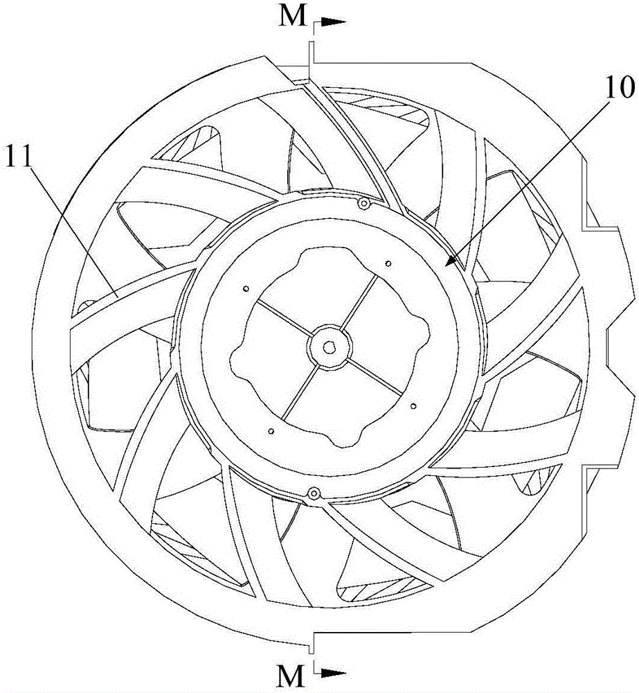
[0064] Refer below Figure 2 to Figure 9 The axial flow fan and its vanes according to some embodiments of the present invention are described.

[0065] The axial fan provided by the embodiments of...


PUM


Abstract

The invention provides an air conditioner, an axial flow fan and a stator blade of the axial flow fan. The stator blade of the axial flow fan comprises a blade body and a lug boss. Particularly, the blade body has a pressure surface and a suction surface. The pressure surface is concave. The suction surface is convex. The blade body is provided with a front edge and a rear edge. The lug boss is arranged at the rear edge of the blade body. The lug boss protrudes from the pressure surface of the blade body. The stator blade of the axial flow fan, provided by the invention, has the advantages that air flow at an air outlet of the axial flow fan can be straightened, the separation phenomenon generated at the air inlet of the axial flow fan can be prevented, trailing edge loss is reduced, and the purpose of reducing the kinetic energy loss of the air flow and the noise of the air flow are achieved.

Description

technical field [0001] The invention relates to the field of air conditioning equipment, in particular to a stator blade of an axial flow fan, an axial flow fan and an air conditioner. Background technique [0002] Existing indoor units, especially cabinet units, generally use centrifugal fans or cross-flow fans as the air supply mechanism. The advantages of high efficiency and large air volume have entered the sight of R&D personnel. However, it has been found through practice that when the axial fan is applied to the air-conditioning cabinet, if figure 1 As shown, the rotor blade is located on the B' side of the D' position, and the stationary vane is located on the A' side of the D' position, and the air flows from the B' side to the A' side, wherein, at the position P1', it corresponds to the axial flow At the trailing edge of the vane of the fan, there will be a large wake loss, which will not only reduce the airflow velocity but also generate noise. In addition, if ...

Claims


Application Information

Patent Timeline
Patent Type & Authority Applications(China)
IPC IPC(8): F04D29/54F04D29/66F04D19/00F24F1/00
CPCF04D19/002F04D29/544F04D29/663F04D29/667F24F1/0029
Inventor 杨彤钟志尧伍敏超孙康杰周何杰
Owner WUHU MATY AIR CONDITIONING EQUIP CO LTD
Why Eureka
Try Eureka