Proportional pressure reducing valve for waterworks

The technology of a constant ratio pressure reducing valve and a water pipe is applied in the field of constant ratio pressure reducing valve, which can solve problems such as large leakage and achieve the effect of preventing water hammer.

Inactive Publication Date: 2016-10-12
KANE KOUGYOU
View PDF5 Cites 5 Cited by
  • Summary
  • Abstract
  • Description
  • Claims
  • Application Information

AI Technical Summary

Problems solved by technology

[0006] However, in the pressure reducing valve with the above structure, there is a problem that if the seal of the reduced diameter portion or the flange deteriorates with use, the water in the flow path in the valve body will flow from the airtight chamber to the outside through the air passage. Leakage, a large amount of water will leak until the pressure reducing valve is repaired or replaced

Method used


Image

  • Proportional pressure reducing valve for waterworks
  • Proportional pressure reducing valve for waterworks
  • Proportional pressure reducing valve for waterworks

Examples


Embodiment Construction

[0029] Hereinafter, an embodiment of the present invention will be explained based on the drawings.

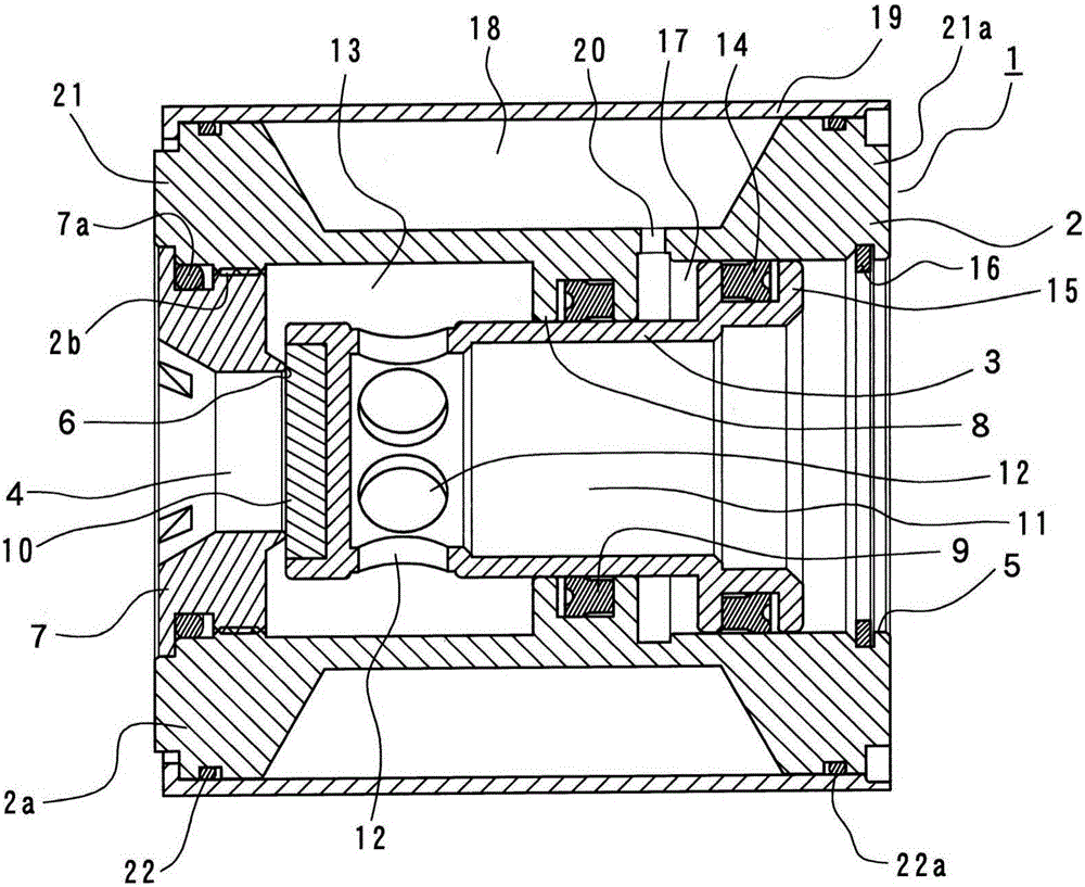
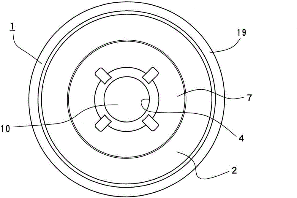
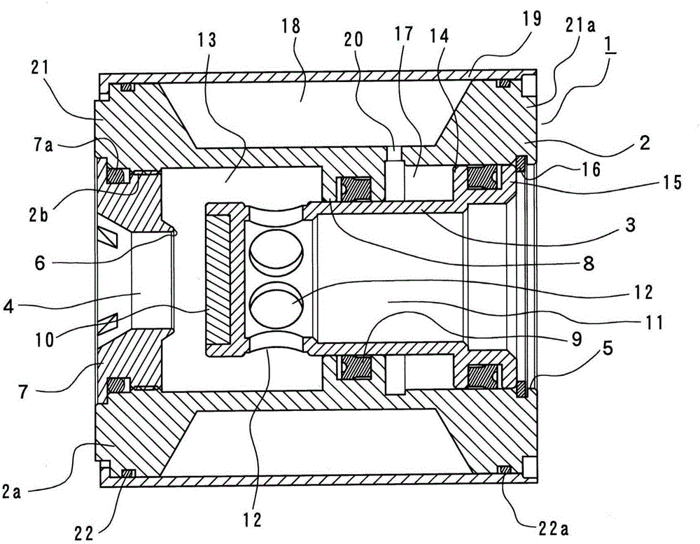
[0030] 1 is a built-in fixed-ratio pressure reducing valve for tap water pipes. The fixed-ratio pressure reducing valve 1 is mainly composed of its valve body 2, and a piston 3 built into the valve body 2. By clamping the valve body 2 in the figure, Use bolts and nuts to fasten the pipe flanges to each other between the pipe flanges for the tap water pipe shown in the figure, thereby arranging the pipes.

[0031] Regarding the valve body 2, its side wall 2a is formed in a thick cylindrical shape, and an inflow port 4 is opened on the front end surface, and an outflow port 5 is opened on the rear end surface, thereby forming a straight line between the inflow port 4 and the outflow port 5. In the flow path, the outflow port 5 is set to have a larger diameter than the inflow port 4, and a valve seat 6 is protrudingly provided on the periphery of the secondary side opening of the infl...


PUM


Abstract

The invention provides a proportional pressure reducing valve for waterworks. A cylindrical valve body is arranged, wherein a water inlet is formed in the front end surface of the valve body and a water outlet is formed in the rear end surface. The diameter of the water outlet is larger than that of the water inlet. An annular convex shrinkage part is formed on the inner wall between the water inlet and the water outlet on the cylindrical valve body in a swelling manner. A piston slidingly and freely penetrates and is inserted in the shrinkage part in an air-tightened manner. A valve part for opening / closing the water inlet is arranged on the end of the piston. A hollow part is arranged on the piston, wherein the base end of the hollow part is opened on the water outlet. A plurality of water flowing openings are formed on periphery of end side, which is more forward from the shrinkage part, of the piston. A flange is formed on the whole periphery of hte base end of the piston and slides on the inner wall, which is more backward than the shrinkage part of the valve body, in an air-tight manner. An air tightness chamber arrnaged between the flange and the shrinkage part is communicated with the hollow chamber. The hollow chamber is formed by air-thightly sealing a concave part formed by sinking peryphery of outer wall of the valve body with a cylindrical cover outside-embedded into the valve body.

Description

Technical field [0001] The present invention relates to a constant-ratio pressure reducing valve for a tap water pipe that maintains a secondary pressure at a predetermined ratio to a primary pressure. Background technique [0002] Patent Document 1 discloses such a constant-ratio pressure reducing valve. [0003] In this pressure reducing valve, a cylindrical valve body is provided. The valve body is provided with an inflow port on the front end surface, and an outflow port set to a larger diameter than the inflow port is opened on the rear end surface. The inner wall between the inflow port and the outflow port is bulged and formed with a ring-shaped reduced diameter portion, in which a piston is inserted slidably in an airtight manner through a seal, and at the end of the piston A valve portion that opens and closes the inflow port is provided. The piston is provided with a hollow portion that opens in the outflow port on the base end side. The end side peripheral surface of th...

Claims


Application Information

Patent Timeline
Patent Type & Authority Applications(China)
IPC IPC(8): F16K17/02F16K15/02F16K47/02
CPCF16K15/02F16K17/02F16K47/02G05D16/103F16K17/24F16K47/023
Inventor 落合优松浦伸幸
Owner KANE KOUGYOU
Why Eureka
Try Eureka