
Touch faucet unit and water supply system with touch faucet unit

A faucet and touch detection technology, which is applied in the field of water supply system and touch faucet unit, can solve the problems of poor anti-interference ability, inconvenient use, short service life, etc., and achieve the effects of preventing failure, saving water and improving sensitivity

Inactive Publication Date: 2016-10-12
宁波顺源电子科技有限公司
View PDF7 Cites 2 Cited by
  • Summary
  • Abstract
  • Description
  • Claims
  • Application Information

AI Technical Summary

Problems solved by technology

[0003] Nowadays, there are many sensor faucets used in public places. The sensor faucet is more sensitive to reflected light, which causes its sensing distance and sensing range to change indefinitely, which will lead to a misunderstanding. When the user uses it beyond the sensing range, If there is no water coming out, the user will mistakenly think it is an ordinary faucet, and then slap the faucet, or twist the faucet, which leads to the damage of the faucet
[0004] The existing touch faucet has a fixed touch point, which is inconvenient to use; while the induction faucet is limited by the sensing range; the standby power consumption of the touch faucet is relatively high, and it is powered by a battery, which has a short service life. Poor anti-interference ability

Method used


Image

  • Touch faucet unit and water supply system with touch faucet unit
  • Touch faucet unit and water supply system with touch faucet unit
  • Touch faucet unit and water supply system with touch faucet unit

Examples


Embodiment Construction

[0030] The above and other technical features and advantages of the present invention will be described in more detail below in conjunction with the accompanying drawings.

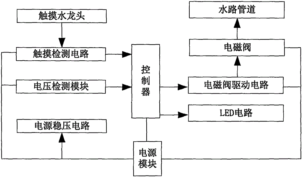
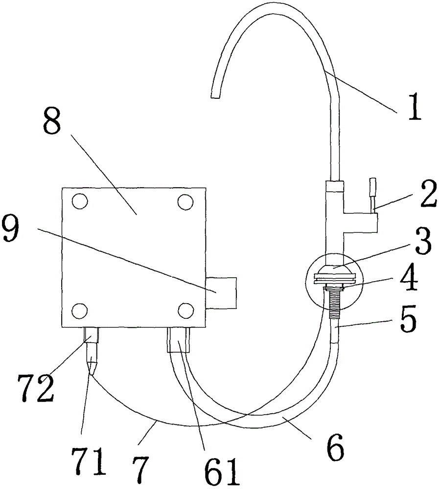
[0031] see figure 1 As shown, it is a schematic diagram of the overall framework of the water supply system of the touch faucet of the present invention, which includes:

[0032] A touch faucet 1 capable of generating touch sensing at all positions on the surface, the touch faucet 1 is connected to a touch detection circuit, and when the touch faucet 1 generates an induction, the induction signal is transmitted to a controller connected to the touch detection circuit;

[0033] It also includes a solenoid valve drive circuit connected to the output end of the controller, the solenoid valve drive circuit controls the action of the solenoid valve 8 connected to it, the solenoid valve 8 is installed on the water pipeline, and the action of the solenoid valve 8 controls the on-off of the waterway .

[0034] I...


PUM


Abstract

The invention relates to a touch faucet unit and a water supply system with the touch faucet unit. The touch faucet unit comprises a touch faucet with all positions on the surface capable of generating touch induction. The touch faucet is connected with a touch detection circuit. When the touch faucet generates induction, induction signals are transmitted to a controller connected with the touch detection circuit. The touch faucet unit further comprises an electromagnetic valve drive circuit connected with the output end of the controller. The electromagnetic valve drive circuit controls an electromagnetic valve connected with the electromagnetic valve drive circuit to act. The electromagnetic valve is installed on a water way pipeline and acts to control a water way to be connected or disconnected. The touch faucet unit further comprises a voltage detection circuit connected with the controller. The voltage of the touch faucet is detected through the voltage detection circuit. By the adoption of the touch faucet unit, water can flow out simply through a touch on the surface of the touch faucet, and water can be stopped through a touch on the surface of the touch faucet again. The touch faucet unit further has an overtime automatic water cut-off function, and a water saving effect is achieved.

Description

technical field [0001] The invention relates to the technical field of touch water outlet, in particular to a touch faucet unit and a water supply system with the unit. Background technique [0002] With the continuous improvement of people's living standards, sanitary facilities will be more humanized and interactive, and market demand is becoming a powerful driving force for the intelligent development of sanitary products. [0003] Nowadays, there are many sensor faucets used in public places. Sensor faucets are more sensitive to reflected light, causing their sensing distance and sensing range to change indefinitely, which will lead to a misunderstanding. When the user uses it beyond the sensing range, If there is no water coming out, the user will mistake it for an ordinary faucet, and slap or twist the faucet, thus causing damage to the faucet. [0004] The existing touch faucet has a fixed touch point, which is inconvenient to use; while the induction faucet is limit...

Claims


Application Information

Patent Timeline
IPC IPC(8): F16K31/06F16K37/00
CPCF16K31/0675F16K37/0025
Inventor 汪锡彪何俊丽
Owner 宁波顺源电子科技有限公司
Learn More