Automatic digital phase demodulation circuit and system with phase difference 0 to 2pi between signals

A digital phase detection and phase difference technology, applied in the field of signal analysis, can solve problems such as inability to detect

Inactive Publication Date: 2016-10-12
GUANGDONG UNIV OF TECH
View PDF8 Cites 2 Cited by
  • Summary
  • Abstract
  • Description
  • Claims
  • Application Information

AI Technical Summary

Problems solved by technology

The existing phase detection circuit can only detect the phase difference of 0~π, if the phase difference between the two information is π~2π, it cannot detect

Method used


Image

  • Automatic digital phase demodulation circuit and system with phase difference 0 to 2pi between signals
  • Automatic digital phase demodulation circuit and system with phase difference 0 to 2pi between signals
  • Automatic digital phase demodulation circuit and system with phase difference 0 to 2pi between signals

Examples


Embodiment Construction

[0027] The technical solutions of the present invention will be further described below in conjunction with the accompanying drawings and through specific implementation methods.

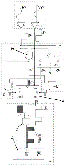
[0028] Such as figure 1 As shown, an automatic digital phase detection circuit with a phase difference between signals of 0 to 2π, including a comparison shaping circuit 1, a detection circuit 2 and a JK trigger 3;

[0029] The comparison shaping circuit 1 is used to convert the two original harmonic signals S m and harmonic signal S r Shaped into a square wave signal Q with the same frequency and phase m and square wave signal Q r , and the square wave signal Q m and square wave signal Q r transmitted to the K input terminal and the J input terminal of the JK flip-flop 3;

[0030] The JK flip-flop 3 is used to output the square wave signal Q m and square wave signal Q r The phase difference between (ie the harmonic signal S m with the harmonic signal S r The phase difference between) the ...


PUM


Abstract

The invention relates to an automatic digital phase demodulation circuit with the phase difference 0 to 2pi between signals, and the circuit is used to detect the phase difference between a harmonic wave signal Sm and a harmonic wave signal Sr. The circuit comprises a comparison shaping circuit, a detection circuit and a Jk trigger; the comparison shaping circuit shapes an original path of harmonic wave signal Sm and an original path of harmonic wave signal Sr into a square wave signal Qm and a square wave signal Qr of the same frequency and phase, and transmits the square wave signal Qm and the square wave signal Qr to the input end K and the input end J of the Jk trigger; the JK trigger outputs a square wave signal OUT of the phase difference between the square wave signal Qm and the square wave signal Qr; and the detection circuit detects the advancing or lagging relation between phases of the square wave signal Qm and the square wave signal Qr as well as the states of the input end K and the input end J of the JK trigger, and sets and resets the JK trigger.

Description

technical field [0001] The invention relates to the field of signal analysis, in particular to an automatic digital phase detection circuit and system with a phase difference between signals of 0 to 2π. Background technique [0002] Automatic digital phase detection, also known as difference frequency digital phase detection, is mainly used to automatically detect the phase difference of two electrical signals, and is widely used in signal analysis, testing instruments and meters and other fields. Automatic digital phase detection has the advantages of high phase measurement accuracy, fast phase measurement speed, easy interface with microcontroller, and automatic data measurement and processing. The existing phase detection circuit can only detect the phase difference of 0~π, if the phase difference between two pieces of information is π~2π, it cannot detect. Contents of the invention [0003] The purpose of the present invention is to propose an automatic digital phase ...

Claims


Application Information

Patent Timeline
Patent Type & Authority Applications(China)
IPC IPC(8): G01R25/00
CPCG01R25/00
Inventor 王晓初卢琛陈新刘强陈云张胜辉高健
Owner GUANGDONG UNIV OF TECH
Why Eureka
Try Eureka