Intelligent switch device based on conventional mechanical switch

A mechanical switch, intelligent switch technology, applied in general control systems, control/regulation systems, program control in sequence/logic controllers, etc., can solve the problems of resource waste, waste, troublesome methods, etc., and save manpower and costs. , improve the degree of intelligence, avoid the effect of waste of resources

Inactive Publication Date: 2016-10-12
NANJING IOT SENSOR TECH
View PDF4 Cites 1 Cited by
  • Summary
  • Abstract
  • Description
  • Claims
  • Application Information

AI Technical Summary

Problems solved by technology

[0002] The wall mechanical switches that have been used for many years have many disadvantages: it is very troublesome to realize double or multiple connections through wiring. If the switch and the lamp (or device) are not in the same place, it is impossible to judge the status of the lamp (or device) switch; After the wiring is completed, if you want to add remote control switches, the amount of work is very large; in the dark night, it is impossible to find the position of the switch accurately; when you want to turn on or off multiple lamps (or devices), you must turn on or off each switch one by one, Let the user repeat the same action many times a day; when the power goes out every time, the owner must turn off all the switches before going out or resting, otherwise the equipment load will always be turned on after the power comes in, causing unnecessary waste
[0003] More and more home appliances use smart control switches to replace traditional mechanical switches. However, when installing most smart switches on the market, users need to remove the traditional mechanical switches at home before replacing them, which will cause waste of resources. , and the removed mechanical switch also loses its use value

Method used


Image

  • Intelligent switch device based on conventional mechanical switch
  • Intelligent switch device based on conventional mechanical switch

Examples


Embodiment 1

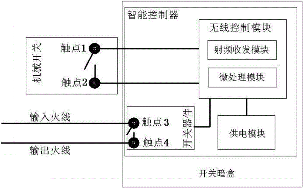
[0022] This embodiment provides an intelligent switch device based on a traditional mechanical switch, taking a pair of contacts as an example, such as figure 1 As shown, it includes a mechanical switch and a switch cassette, the mechanical switch includes contact 1 and contact 2, an intelligent controller is installed in the switch cassette, and the intelligent controller is connected to the input live wire and the output live wire;

[0023] The intelligent controller includes a wireless control module, a power supply module and a switching device. The wireless control module includes a radio frequency transceiver module and a microprocessing module. The power supply module supplies power for the intelligent controller as a whole. The drive signal, contact 1 and contact 2 are connected to the two IO ports of the micro-processing module as a group of signals, and the live wire input and live wire output are respectively connected to the contact 3 and contact 4 of the switch dev...


PUM


Abstract

The invention discloses an intelligent switch device based on a conventional mechanical switch. The intelligent switch device comprises the mechanical switch and a switch cassette. The mechanical switch comprises a contact 1 and a contact 2. The switch cassette is internally provided with an intelligent controller which is connected with an input live wire and an output live wire. The intelligent controller comprises a wireless control module, a power supply module and a switch device. The wireless control module comprises a radio frequency transmit-receive module and a microprocessing module. The power supply module supplies power to the whole intelligent controller. The driving end of the switch device is connected with the microprocessing module and used for receiving a driving signal. The contact 1 and the contact 2 act as a set of signals to be accessed to the two IO ports of the microprocessing module. A live wire input end and a live wire output end are respectively connected with the contact 3 and the contact 4 of the switch device. According to the device, reconstruction of original wiring is avoided for users, and the original conventional mechanical switch can be continuously used so that waste of resources can be reduced and reconstruction of the conventional mechanical switch to the intelligent switch can be easily realized.

Description

technical field [0001] The invention belongs to the technical field of intelligent switches, and relates to an intelligent switch device based on a traditional mechanical switch. Background technique [0002] The wall mechanical switches that have been used for many years have many disadvantages: it is very troublesome to realize double or multiple connections through wiring. If the switch and the lamp (or device) are not in the same place, it is impossible to judge the status of the lamp (or device) switch; After the wiring is completed, if you want to add remote control switches, the amount of work is very large; in the dark night, it is impossible to find the position of the switch accurately; when you want to turn on or off multiple lamps (or devices), you must turn on or off each switch one by one, Let the user repeat the same action many times a day; when the power goes out every time, the owner must turn off all the switches before going out or resting, otherwise the ...

Claims


Application Information

Patent Timeline
Patent Type & Authority Applications(China)
IPC IPC(8): G05B19/05
CPCG05B19/054G05B2219/1103
Inventor 朱俊岗朱峰朱俊岭余建美
Owner NANJING IOT SENSOR TECH
Why Eureka
Try Eureka