

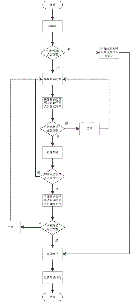
Searching method of shortest path passing by necessary peak points
A technology of the shortest path and search method, which is applied in the fields of physics and path search, can solve the problems of slow solution speed, inability to find the optimal path stably, and the inability to find the path, etc., and achieve the effect of reducing time capability and search scale
- Summary
- Abstract
- Description
- Claims
- Application Information
AI Technical Summary
Problems solved by technology
Method used
Image

Examples
test Embodiment Cas
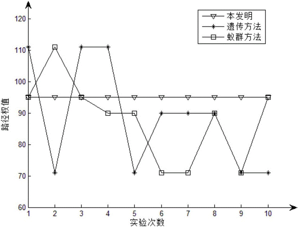
[0109] figure 2 For the test case Case1, it is a broken line comparison diagram of 10 test path weights using the present invention, the genetic method and the ant colony method.
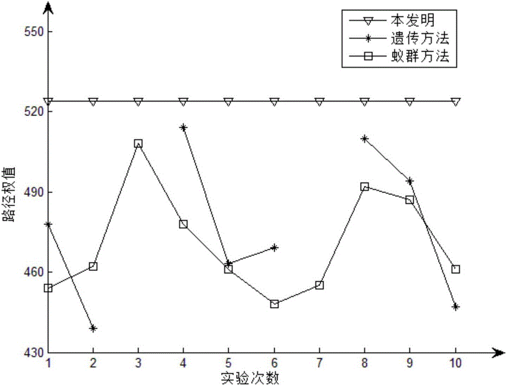
[0110] image 3 It is a line comparison diagram of test path weights for 10 times by using the present invention, the genetic method and the ant colony method for the test case Case2.
[0111] Figure 4 For test case Case3, it is a broken-line comparison diagram of 10 test path weights using the present invention, the genetic method and the ant colony method.
[0112] figure 2 , image 3 and Figure 4 The abscissa in represents the number of simulation experiments, and the ordinate represents the weight obtained from each simulation experiment. figure 2 , image 3 and Figure 4 Among them, the broken line marked with ▽ represents the broken line diagram of the 10 simulation experiment path weights of the present invention, the broken line marked with * represents the broken line diagram o...
test Embodiment Ca
[0115] Figure 5 For the test case Case1, it is a broken line comparison chart of the time used for 10 tests using the present invention, the genetic method and the ant colony method;
[0116] Figure 6 For the test case Case2, the broken line comparison diagram of the time used for 10 tests by using the present invention, the genetic method and the ant colony method 3 methods;
[0117] Figure 7 For the test case Case3, it is a broken-line comparison graph of the time spent in performing 10 tests by using the present invention, the genetic method and the ant colony method.
[0118] Figure 5 , Figure 6 and Figure 7 The abscissa in represents the number of simulation experiments, and the ordinate represents the time spent in each simulation experiment. Figure 5 , Figure 6 And in Fig. 8, the broken line represented with ○ marks the broken line graph of the time used for 10 simulation experiments of the present invention, and the broken line represented with ☆ marks t...
PUM
 Abstract
Description
Claims
Application Information