Standing wave demonstration method

A demonstration method and standing wave technology, applied in the field of physical experiments, can solve problems such as inability to use continuously, unable to form continuous waveforms, prone to safety accidents, etc., to avoid potential safety hazards, improve performance, and ensure the effect of continuous demonstration.

Active Publication Date: 2016-10-12
CHONGQING UNIV OF TECH
View PDF10 Cites 0 Cited by
  • Summary
  • Abstract
  • Description
  • Claims
  • Application Information

AI Technical Summary

Problems solved by technology

[0005] 1. Due to the use of flammable gas to demonstrate standing waves, this will lead to two main problems. One is that the safety of indoor demonstrations is poor, and safety accidents are prone to occur; the other is that cylinder 1 and The ejection branch pipe 1a will be very hot. In order to achieve cooling, it must be stopped after a period of demonstration, and the demonstration will be performed after the cylinder 1 and the ejection branch pipe 1a are completely cooled, so that it cannot be used continuously;
[0006] 2. The existing demonstrator is equidistantly equipped with a group of ejection branch pipes 1a, so that only the peaks and troughs can be seen, and continuous waveforms cannot be formed, which leads to the need to improve the demonstration effect

Method used


Image

  • Standing wave demonstration method
  • Standing wave demonstration method
  • Standing wave demonstration method

Examples


Embodiment Construction

[0025] Below in conjunction with accompanying drawing and embodiment the present invention will be further described:

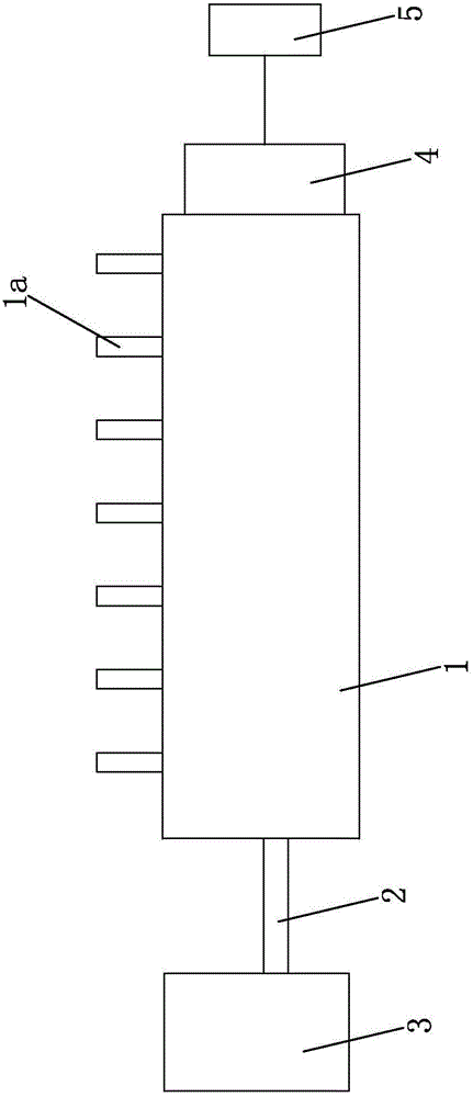
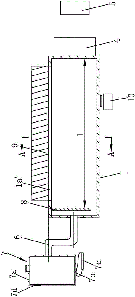
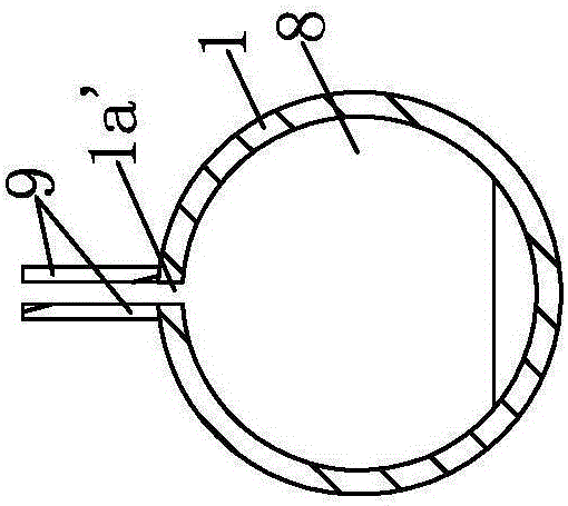
[0026] Such as figure 2 , 3 Shown, a kind of standing wave demonstration method is characterized in that comprising the steps:

[0027] Step a: Design a standing wave demonstration device, the standing wave demonstration device is mainly composed of a cylinder 1, a sound wave generator 4, a frequency modulator 5, a droplet inlet tube 6, an ultrasonic atomization component 7, a radial baffle 8, a transparent The baffle plate 9 and the liquid collection tank 10 constitute. Wherein, the material of cylinder 1 can be stainless steel or plastic, and its material is not required to be high temperature resistant metal. For the convenience of observation, the cylinder 1 is designed as a transparent cylinder. Both ends of the cylinder 1 are sealed, and a sound wave generating device 4 is installed at the right end of the cylinder, and the sound wave generating de...


PUM


Abstract

The invention discloses a standing wave demonstration method. The method comprises the steps that a. a standing wave demonstration device is designed; b. an ultrasonic atomization module is turned on to ultrasonic-atomize liquid into fogdrops, and the fogdrop are introduced into a cylinder through a fogdrop inlet tube; and c. a sound wave generating device and a frequency converter are turned on, and the frequency converter is controlled to adjust the frequency of sound waves emitted by the sound wave generating device. According to the standing wave demonstration device, the right end of the cylinder is provided with the sound wave generating device; the frequency converter is connected with the sound wave generating device; the left end of the cylinder is connected with the ultrasonic atomizing module through the fogdrop inlet tube; an elongated ejection notch is axially arranged at the upper part of the cylinder wall; and a transparent baffle plate is symmetrically arranged on front and rear sides of the elongated ejection notch. According to the invention, a traditional demonstration instrument which displays standing waves by igniting a combustible gas is abandoned; the fogdrops after ultrasonic atomization are used to display the standing waves; safety hidden fire trouble can be avoided; and the cylinder is prevented from burning hot.

Description

technical field [0001] The invention belongs to the field of physical experiments, in particular to a standing wave demonstration method. Background technique [0002] Such as figure 1 As shown, the existing standing wave demonstration device includes a cylinder 1 and a frequency modulator 5, wherein the two ends of the cylinder 1 are sealed, and the left end of the cylinder 1 is connected with the combustible gas supply device 3 through the air inlet pipe 2, and the upper part of the cylinder 1 is along the A row of ejection branch pipes 1a is provided at equal distances in the axial direction, and both the cylinder 1 and the ejection branch pipes 1a are metal pipes. The right end of the cylinder 1 is equipped with a sound wave generating device 4 which is connected with the frequency modulator 5 . [0003] The method corresponding to the above-mentioned standing wave demonstration device is as follows: the combustible gas supply device 3 delivers combustible gas (such as...

Claims


Application Information

Patent Timeline
Patent Type & Authority Applications(China)
IPC IPC(8): G09B23/14
CPCG09B23/14
Inventor 龚恒翔梁霄
Owner CHONGQING UNIV OF TECH
Why Eureka
Try Eureka