A self-adaptively adjustable yag solid-state laser and its application method

An adaptive adjustment and solid-state laser technology, which is applied in the field of YAG lasers, can solve the problems of adjustment lag, unstable quality, time-consuming and labor-intensive problems, and achieve the effects of reducing experience requirements, improving optical path reliability, and avoiding mechanical deformation.

Active Publication Date: 2019-04-26
东莞华松创新科技有限公司
View PDF5 Cites 0 Cited by
  • Summary
  • Abstract
  • Description
  • Claims
  • Application Information

AI Technical Summary

Problems solved by technology

[0003] Because it is impossible to check the position of the red light spot in real time, the adjustment often lags behind, and manual adjustment of the full mirror and half mirror is difficult, time-consuming and laborious, and requires experienced staff to operate, and it is difficult to fully achieve accurate position
[0004] The center of the cutting laser beam is constantly changing, and the quality is unstable, which directly affects the quality indicators of laser slitting and cutting

Method used


Image

  • A self-adaptively adjustable yag solid-state laser and its application method
  • A self-adaptively adjustable yag solid-state laser and its application method
  • A self-adaptively adjustable yag solid-state laser and its application method

Examples


Embodiment Construction

[0052] Embodiment of adaptively adjusted YAG solid-state laser

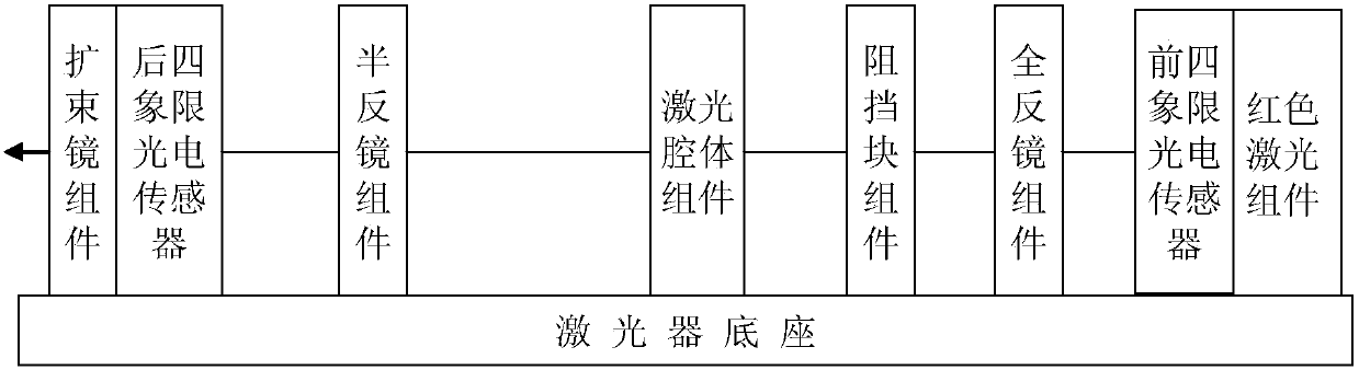
[0053] The structure of this adaptively adjusted YAG solid-state laser embodiment is as follows figure 1 As shown, it includes a red laser component, a full mirror component, a laser cavity component, a half mirror component and a beam expander component installed on the laser base in sequence from back to front, and the centers of the above components are all on a straight line optical axis , the laser light generated by the laser cavity assembly is sent out from the front end of the laser through the full reflection mirror, half reflection mirror and beam expander, which is the laser cutting head. The red laser component installed at the end of the laser is a red laser device installed on the H fine-tuning frame; the full-mirror component is a full-reflective mirror mounted on the Q fine-tuning frame, and the half-mirror component is a half-mirror mounted on the B fine-tuning frame mirror. The red positioning...


PUM


Abstract

The invention relates to a self-adaptive adjustment YAG solid-state laser device and an application method thereof. The YAG solid-state laser device comprises assemblies such as a red laser device, a total reflective mirror, a laser cavity body, a semi-reflective mirror and a beam expanding mirror which are arranged on a laser device base and positioned on the same optical axis, wherein the red laser device, the total reflective mirror and the semi-reflective mirror are each installed on a fine-adjusting frame controlled by a single chip microcomputer, a movable blocking sheet controlled by the single chip microcomputer is arranged between the laser cavity body and the total reflective mirror, and a four-quadrant photoelectric sensor connected with the single chip microcomputer is installed in each of the red laser device and the beam expanding mirror. The application method comprises the pre-adjusting step of adjusting the red laser device to a reference position by the single chip microcomputer according to information of the four-quadrant photoelectric sensors firstly, adjusting the total reflective mirror while blocking red laser irradiated to the semi-reflective mirror by using the blocking sheet, and then adjusting the semi-reflective mirror after moving the blocking sheet away. The self-adaptive adjustment in operation includes the adjustment of the total reflective mirror and the adjustment of the semi-reflective mirror. The self-adaptive adjustment YAG solid-state laser device and the application method thereof achieve automatic adjustment of an optical path of the laser device according to positions of red laser spots, enhance the reliability of the optical path, ensure the laser quality and improve the laser processing precision.

Description

technical field [0001] The invention belongs to the field of YAG lasers, in particular to an adaptively adjusted YAG solid-state laser and a use method thereof. Background technique [0002] Laser cutting is one of the important thermal cutting methods for modern sheet metal processing. The traditional lasers used include the laser-generating cavity, total reflection mirror, half reflection mirror and beam expander are all installed on the base of the laser, and their center points should be in line theoretically, that is, the optical axis. The laser generated by the cavity is sent out from the front end of the laser through the full mirror, half mirror and beam expander, which is the laser cutting head. Only when the center of the full mirror and half mirror is on the optical axis can the reflected laser be concentrated into a high-intensity laser beam, but mechanical deformation, thermal deformation of the lens, mechanical vibration during cutting operations, etc. will ca...

Claims


Application Information

Patent Timeline
Patent Type & Authority Patents(China)
IPC IPC(8): H01S3/101H01S3/105H01S3/107
CPCH01S3/101H01S3/105H01S3/1075
Inventor 徐剑飞
Owner 东莞华松创新科技有限公司
Why Eureka
Try Eureka