A low voltage ride through control method and system based on mmc photovoltaic grid-connected inverter
A low-voltage ride-through and control method technology, applied in photovoltaic power generation, AC network circuits, electrical components, etc., can solve problems such as capacitor voltage fluctuations, and achieve the effect of increasing output reactive power
- Summary
- Abstract
- Description
- Claims
- Application Information
AI Technical Summary
Problems solved by technology
Method used
Image
Examples
specific Embodiment approach
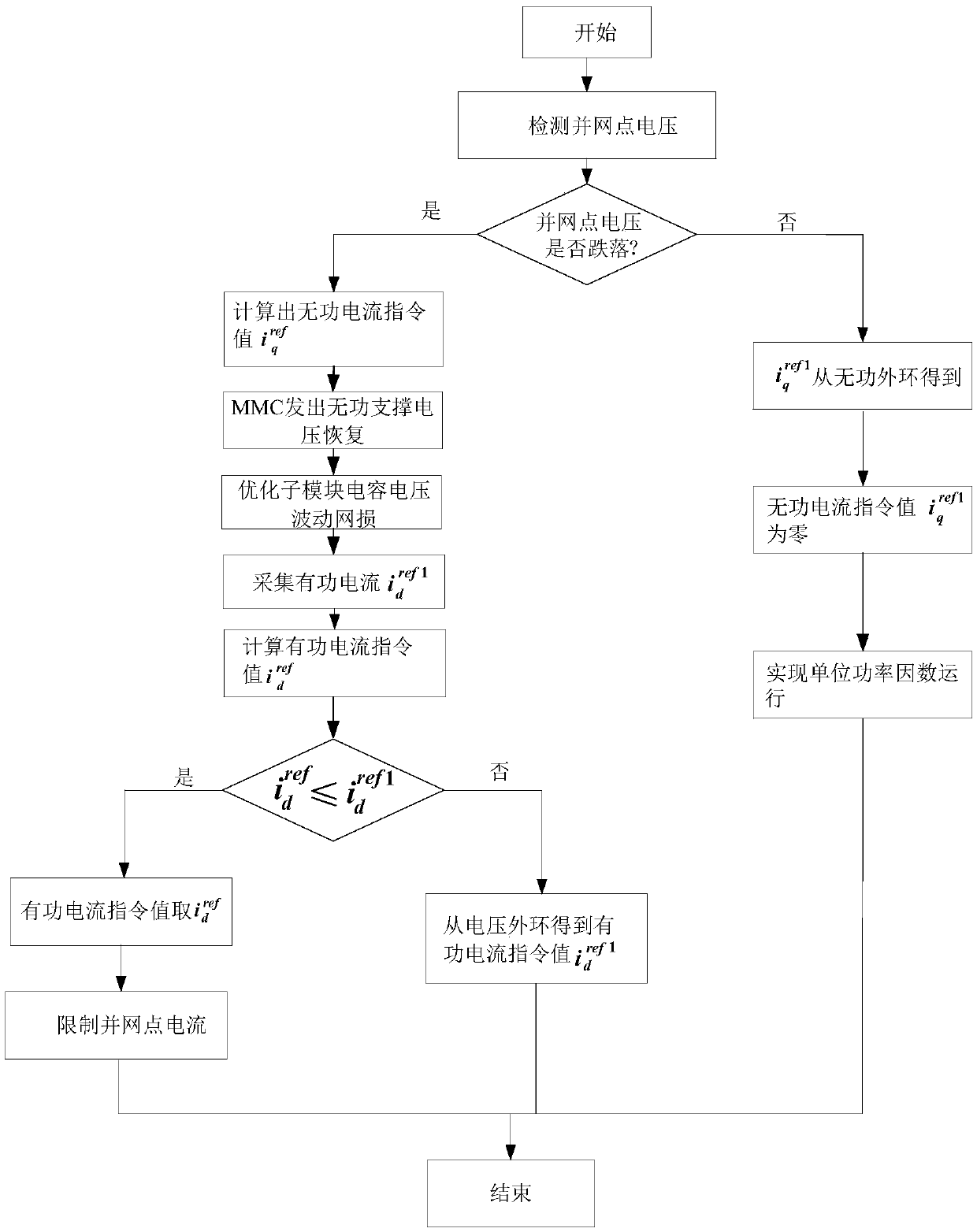
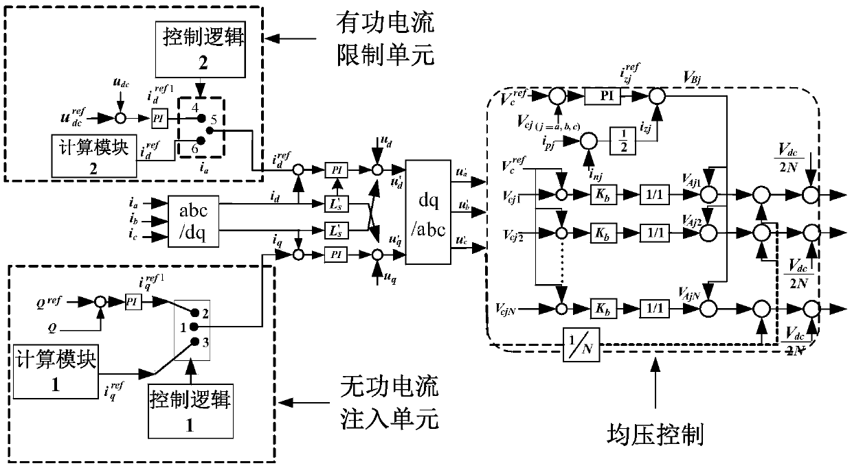
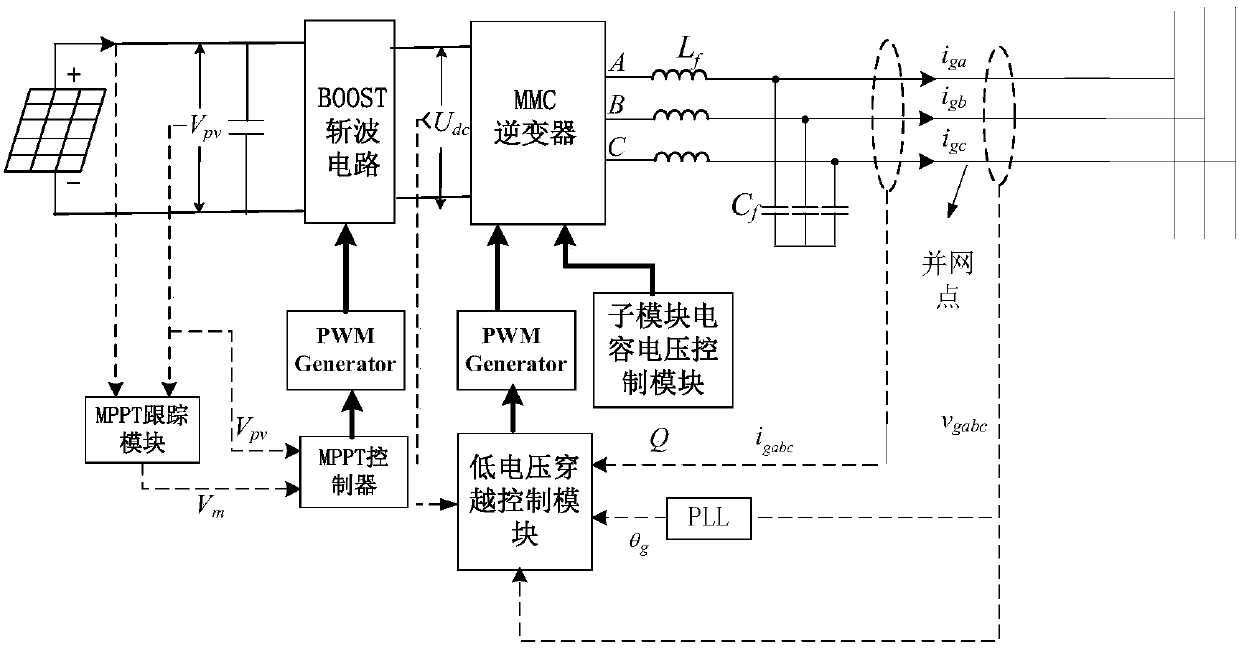
[0049] The present invention provides a low-voltage ride-through control method and system for a photovoltaic grid-connected inverter. On the basis of the traditional double-closed-loop vector control of the current inner loop voltage outer loop, when the voltage drop at the grid-connected point is detected, the reactive power The combination of current injection, control of sub-module capacitor voltage fluctuation range and limitation of active current realizes low-voltage ride-through and ensures safe grid-connected operation of photovoltaics. The specific implementation is as follows:
[0050] When the grid-connected point voltage drop is detected, the reactive current command value is redistributed to achieve reactive current injection; by adding a new active current command value To redistribute the command value of the active current value to limit the active current; and adjust the fluctuation range of the capacitor voltage of the MMC sub-module by optimizing the bri...
Embodiment 1
[0058] Embodiment 1, the method for optimizing bridge arm current:
[0059] In the power grid, there are three phases A, B, and C. Taking phase A as a representative, the corresponding formulas and corresponding values of phase B and C can be obtained in the same way; the capacitor voltage of the MMC sub-module is:
[0060]
[0061]
[0062] In the formula, U cpa In order to optimize the capacitor voltage of the sub-module on the front A phase, U cna In order to optimize the capacitor voltage of the sub-module in the front A phase, U dc is the DC side voltage, P dc is the DC side power, K is the voltage modulation coefficient, is the power factor.
[0063] From the analysis of the above formula, it can be seen that under the condition of keeping the transmission power constant, the capacitance value of the sub-module and the DC voltage constant, the fluctuation of the capacitor voltage of the sub-module is mainly affected by the power factor The smaller the powe...
Embodiment 2
[0073] Embodiment 2, the method of controlling the reference voltage of the sub-module:
[0074] When the number of sub-modules of the MMC reaches a certain number, there is the following formula for the fluctuation of the sub-module capacitor voltage:
[0075]
[0076] In the formula, N represents the number of sub-modules of the upper bridge arm, and U cref Indicates the sub-module reference voltage, C is the capacitance, Δu smc_pa Indicates the voltage fluctuation of the upper bridge arm capacitor, P pa Indicates the active power of the upper bridge arm.
[0077] From the analysis of the above formula, it can be known that when the number of sub-modules, capacitance and power of the upper bridge arm are constant, the reference voltage of the sub-module is U cref The change of will affect the capacitor voltage fluctuation, that is, the sub-module reference voltage U cref becomes larger, the capacitor voltage fluctuates Δu smc_pa Decrease; sub-module reference voltage...
PUM
 Abstract
Description
Claims
Application Information
 - R&D
- Intellectual Property
- Life Sciences
- Materials
- Tech Scout
- Unparalleled Data Quality
- Higher Quality Content
- 60% Fewer Hallucinations
Browse by: Latest US Patents, China's latest patents, Technical Efficacy Thesaurus, Application Domain, Technology Topic, Popular Technical Reports.
© 2025 PatSnap. All rights reserved.Legal|Privacy policy|Modern Slavery Act Transparency Statement|Sitemap|About US| Contact US: help@patsnap.com


