MMC-based low-voltage ride through control method and system of photovoltaic grid-connected inverter

A low-voltage ride-through and control method technology, applied in photovoltaic power generation, AC network circuits, electrical components, etc., can solve problems such as capacitor voltage fluctuations

Active Publication Date: 2016-10-12
NANJING INST OF TECH
View PDF5 Cites 13 Cited by
  • Summary
  • Abstract
  • Description
  • Claims
  • Application Information

AI Technical Summary

Problems solved by technology

[0005] In order to solve the problem of capacitor voltage fluctuations of MMC sub-modules, the present invention proposes an improved low-voltage ride-through contro

Method used


Image

  • MMC-based low-voltage ride through control method and system of photovoltaic grid-connected inverter
  • MMC-based low-voltage ride through control method and system of photovoltaic grid-connected inverter
  • MMC-based low-voltage ride through control method and system of photovoltaic grid-connected inverter

Examples


specific Embodiment approach

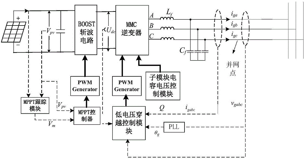
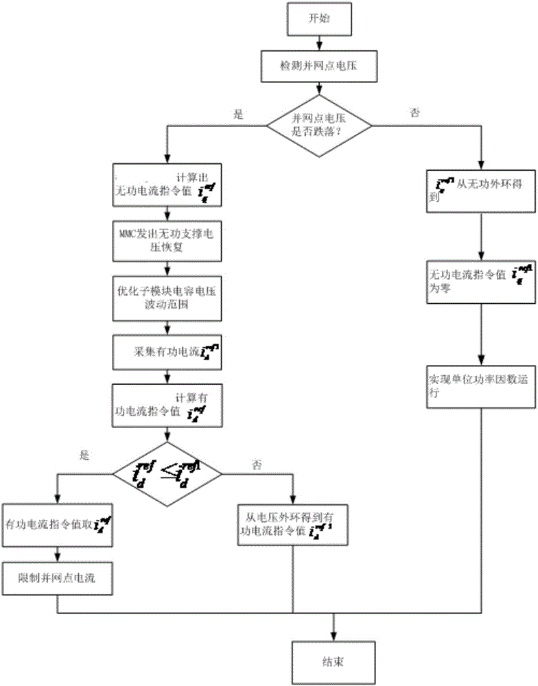
[0049] The present invention provides a low-voltage ride-through control method and system for a photovoltaic grid-connected inverter. On the basis of the traditional double-closed-loop vector control of the current inner loop voltage outer loop, when the voltage drop at the grid-connected point is detected, the reactive power The combination of current injection, control of sub-module capacitor voltage fluctuation range and limitation of active current realizes low-voltage ride-through and ensures safe grid-connected operation of photovoltaics. The specific implementation is as follows:

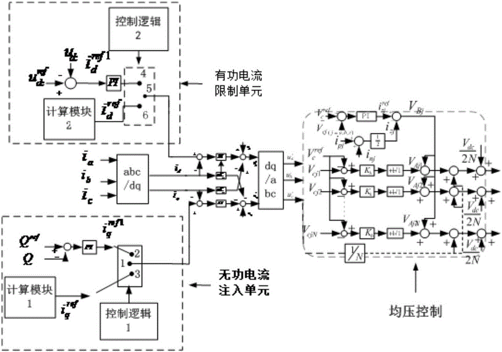
[0050] When the grid-connected point voltage drop is detected, the reactive current command value is redistributed to achieve reactive current injection; by adding a new active current command value To redistribute the command value of the active current value to limit the active current; and adjust the fluctuation range of the capacitor voltage of the MMC sub-module by optimizing the bri...

Embodiment 1

[0058] Embodiment 1, the method for optimizing bridge arm current:

[0059] In the power grid, there are three phases A, B, and C. Taking phase A as a representative, the corresponding formulas and corresponding values ​​of phase B and C can be obtained in the same way; the capacitor voltage of the MMC sub-module is:

[0060]

[0061]

[0062] In the formula, U cpa In order to optimize the capacitor voltage of the sub-module on the front A phase, U cna In order to optimize the capacitor voltage of the sub-module in the front A phase, U dc is the DC side voltage, P dc is the DC side power, K is the voltage modulation coefficient, is the power factor.

[0063] From the analysis of the above formula, it can be seen that under the condition of keeping the transmission power constant, the capacitance value of the sub-module and the DC voltage constant, the fluctuation of the capacitor voltage of the sub-module is mainly affected by the power factor The smaller the powe...

Embodiment 2

[0073] Embodiment 2, the method of controlling the reference voltage of the sub-module:

[0074] When the number of sub-modules of the MMC reaches a certain number, there is the following formula for the fluctuation of the sub-module capacitor voltage:

[0075] Δu s m c _ p a ≈ ∫ P p a d t NCU c r e f

[0076] In the formula, N represents the number of sub-modules of the upper bridge arm, and U cref Indicates the sub-module reference voltage, C is the capacitance, Δu smc_pa Indicates the voltage fluctuatio...


PUM


Abstract

The invention provides an MMC-based low-voltage ride through control method and system of a photovoltaic grid-connected inverter. On the basis of traditional inner current loop and outer voltage loop double closed-loop vector control, when a grid-connected point voltage drop is detected, a reactive current instruction value as shown in the specification is redistributed by judging the voltage drop degree to achieve reactive current injection; the capacitor voltage fluctuation range of an MMC sub-module is adjusted by optimizing bridge arm current; a new active current instruction value is introduced to limit active current; and the active current is limited, so that low-voltage ride through is achieved and safe photovoltaic grid-connected operation is ensured. Through the system and the method, capacitor voltage fluctuation is suppressed by optimizing bridge arm loop current; output reactive power is increased; and the capacitor voltage fluctuation range of the sub-module is optimized by controlling reference voltage of the sub-module, so that the problem that the capacitor voltage fluctuation of the MMC sub-module is out of the limit during reactive injection is solved; and low-voltage ride through is smoothly achieved.

Description

technical field [0001] The invention relates to the field of power electronics, in particular to the field of low-voltage ride-through control of photovoltaic grid-connected inverters based on MMC. Background technique [0002] With the development of human society and economy, energy is also increasingly demanded by human beings. However, on the one hand, there is an ever-increasing demand for energy, and on the other hand, with the continuous exploitation of limited fossil energy, the reserves are constantly decreasing and becoming exhausted. Rapidly growing energy demand, limited fossil resources, dependence on traditional fossil resources and increasingly serious environmental problems need to be resolved urgently. In order to achieve sustainable social and economic development, the development and utilization of renewable new energy such as solar energy and wind energy has become an inevitable choice for human beings. Solar energy is a kind of clean and renewable ener...

Claims


Application Information

Patent Timeline
IPC IPC(8): H02J3/38
CPCH02J3/383Y02E10/56
Inventor 李先允姜婷婷倪喜军王书征
Owner NANJING INST OF TECH
Why Eureka
Try Eureka