Video photographing control device and method, and unmanned aerial vehicle
A technology for video shooting and control devices, applied in the field of drones, can solve the problems of reduced user experience, limited opportunities, complicated operation methods, etc., to achieve the effect of improving user experience
- Summary
- Abstract
- Description
- Claims
- Application Information
AI Technical Summary
Problems solved by technology
Method used
Image

Examples
no. 1 example
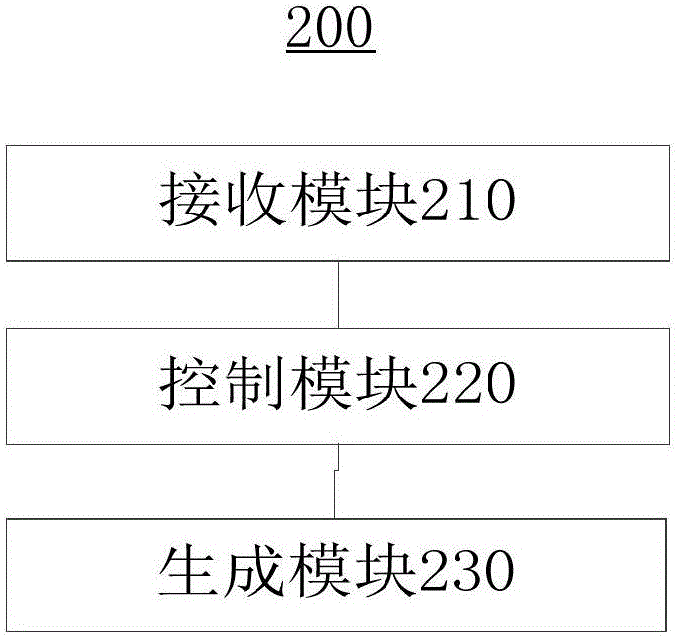
[0026] see figure 2 , shows a functional block diagram of the video shooting control device 200 provided by the preferred embodiment of the present invention. The video shooting control device 200 provided by the preferred embodiment of the present invention includes: a receiving module 210 , a control module 220 and a generating module 230 .
[0027] The receiving module 210 is used for receiving a trigger instruction.
[0028] In the embodiment of the present invention, the user can pre-set a preset shooting mode for the drone 100 through a remote control terminal such as a universal remote control of the drone or a smart phone. Point surround shooting, UAV accelerated flight shooting, camera flying at a preset angle with the horizontal plane, etc., wherein the straight line long lens shooting means that the UAV moves along a straight line, and the camera takes a relatively long time to continuously Shooting to form a relatively complete lens segment; shooting around a po...
no. 2 example
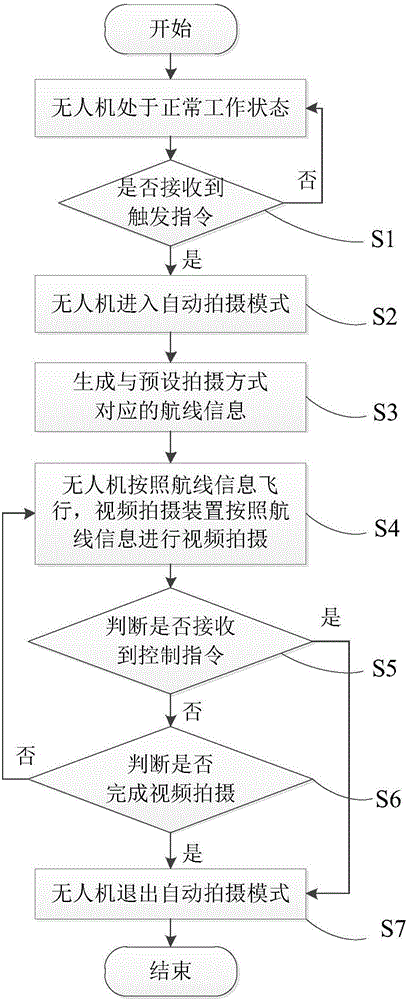
[0046] image 3 A flow chart of a video shooting control method provided by a preferred embodiment of the present invention is shown. The video shooting control method provided by the preferred embodiment of the present invention includes the following steps:
[0047] Step S1, receiving a trigger instruction.
[0048] In the embodiment of the present invention, step S1 may be performed by the receiving module 210 .
PUM
 Abstract
Description
Claims
Application Information