An oil control valve characterized by end portion oil supply

An oil control valve and oil supply technology, which is applied to control the pressure of lubricants, valve details, multi-way valves, etc., can solve the problems of easy fatigue and fracture of the filter screen 7 and increased bending stress of the filter screen 7, so as to achieve less fatigue. The effect of fracture, hydraulic pressure reduction, and durability improvement

Active Publication Date: 2016-10-19
SCHAEFFLER TECH AG & CO KG
View PDF3 Cites 0 Cited by
  • Summary
  • Abstract
  • Description
  • Claims
  • Application Information

AI Technical Summary

Problems solved by technology

[0004] However, the existing oil control valve for oil supply at the end has the following disadvantages: when the oil control valve is working, the filter screen 7 of the filter 5 will be subjected to the circulating oil pressure of the hydraulic oil, causing the filter screen 7 to be easily fatigued and broken
Especially when the particles in the hydraulic oil are blocked in the meshes of the filter screen 7, the bending stress of the filter screen 7 will increase sharply, making this problem even more serious

Method used


Image

  • An oil control valve characterized by end portion oil supply
  • An oil control valve characterized by end portion oil supply
  • An oil control valve characterized by end portion oil supply

Examples


Embodiment Construction

[0021] In order to make the above objects, features and advantages of the present invention more comprehensible, specific embodiments of the present invention will be described in detail below in conjunction with the accompanying drawings.

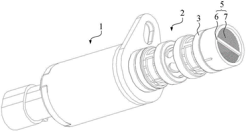
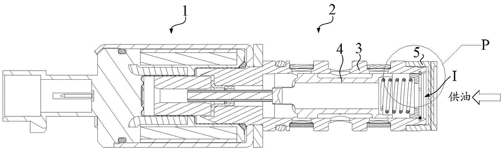
[0022] combine Figure 4 to Figure 5 As shown, the oil control valve for oil supply at the end of this embodiment includes two parts: a proportional electromagnet 10 and a hydraulic body 20 . Wherein, the proportional electromagnet 10 includes a movable armature 100 . The hydraulic body 20 includes: a valve body 200; a push rod 201, a movable piston 202, a compression spring 203, a spring seat 204, and a snap ring 205 arranged in sequence along the axial direction in the valve body 200; a filter 210; an elastic member 220.

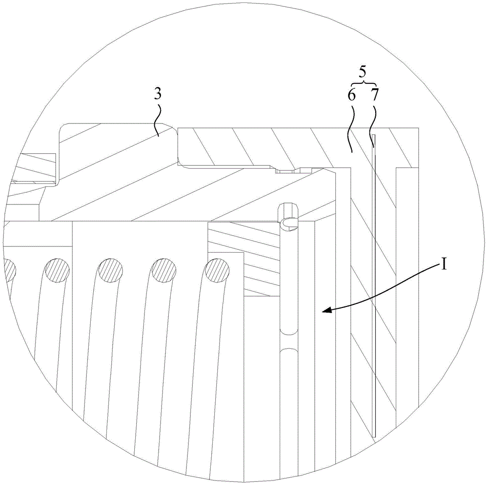
[0023] The valve body 200 has an oil inlet I located at the axial end, and a shoulder 206 protruding radially outward on the outer peripheral surface of the valve body 200, and the other end of the valve body 200 in ...


PUM


Abstract

The invention provides an oil control valve characterized by end portion oil supply. The oil control valve comprises a valve body, a filter, a protruding shoulder and an elastic member. The valve body is provided with an oil inlet at an axial end portion. The filter comprises an annular main body portion and a filter screen fixedly mounted to the annular main body portion; the annular main body portion sleeves the outer peripheral surface of the end portion and the filter screen is located on the outer side of the oil inlet. The protruding shoulder is located on the outer peripheral surface of the valve body and protrudes outward in the radial direction. The protruding shoulder and the annular main body portion are arranged to be spaced from each other in the axial direction of the valve body. The elastic member is located in the gap between the protruding shoulder and the annular main body portion. The annular main body portion can move in the axial direction of the valve body and is axially in anti-disconnecting fit with the valve body. When moving towards the protruding shoulder in the axial direction, the annular main body portion can extrude the elastic member to make the elastic member deform elastically. The technical solution solves the problem that a filter screen of a filter in the conventional oil control valve characterized by end portion oil supply is liable to breakage because of fatigue.

Description

technical field [0001] The invention relates to the field of an oil control valve (OCV for short) used in a variable valve timing (Variable Valve Timing, VVT for short) system, in particular to an oil control valve for supplying oil at an end. Background technique [0002] The oil control valve is one of the core components of the variable valve timing system. According to the oil supply mode, the existing oil control valves are divided into two types: end oil supply oil control valves and side oil supply oil control valves. [0003] combine Figure 1 to Figure 2 As shown, an existing oil control valve for oil supply at the end includes two parts: a proportional electromagnet 1 and a hydraulic body 2 . Wherein, the hydraulic body 2 includes a valve body 3 , a piston 4 movably located in the valve body 3 , and a filter 5 . combine Figure 2 to Figure 3 As shown, the valve body 3 has an oil inlet 1 located at the axial end, the filter 5 has an annular main body 6, and a fil...

Claims


Application Information

Patent Timeline
Patent Type & Authority Applications(China)
IPC IPC(8): F01M1/16F01L1/34
CPCF01L1/3442F01L2001/34426F01L2303/00F16K11/0716F16K27/041F16K27/048F16K31/0613F01L1/344
Inventor 张文豪
Owner SCHAEFFLER TECH AG & CO KG
Why Eureka
Try Eureka