Electrically driven turnover welding device for bent pipes

A welding device and a flip-up technology, applied in the field of pipe fitting welding and machining, can solve the problems of large space occupation, high cost, long time consumption, etc., and achieve the effect of saving overhead and cost, reducing space occupation and ensuring welding accuracy.

Active Publication Date: 2016-10-26
GUIZHOU ZUNYI CHI YU PRECISION MACHINERY MFG
View PDF7 Cites 1 Cited by
  • Summary
  • Abstract
  • Description
  • Claims
  • Application Information

AI Technical Summary

Problems solved by technology

[0003] The purpose of the present invention is to provide an electrically driven reversible welding device for bending pipe fittings, so as to solve the problems of long time consumption, low efficiency, easy bending or deviation of pipe fittings, large errors and poor finished products in the welding of existing bending pipe fittings. Problems of low pass rate, high cost and large space occupation

Method used


Image

  • Electrically driven turnover welding device for bent pipes
  • Electrically driven turnover welding device for bent pipes
  • Electrically driven turnover welding device for bent pipes

Examples


Embodiment Construction

[0015] The technical scheme of the present invention will be further described below in conjunction with the accompanying drawings, but the required protection scope is not limited to the description;

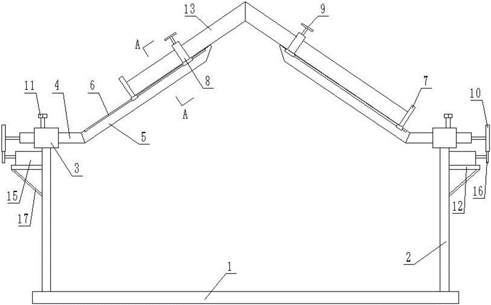
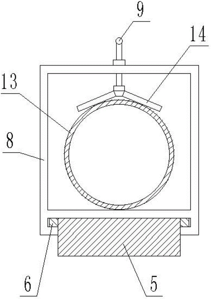
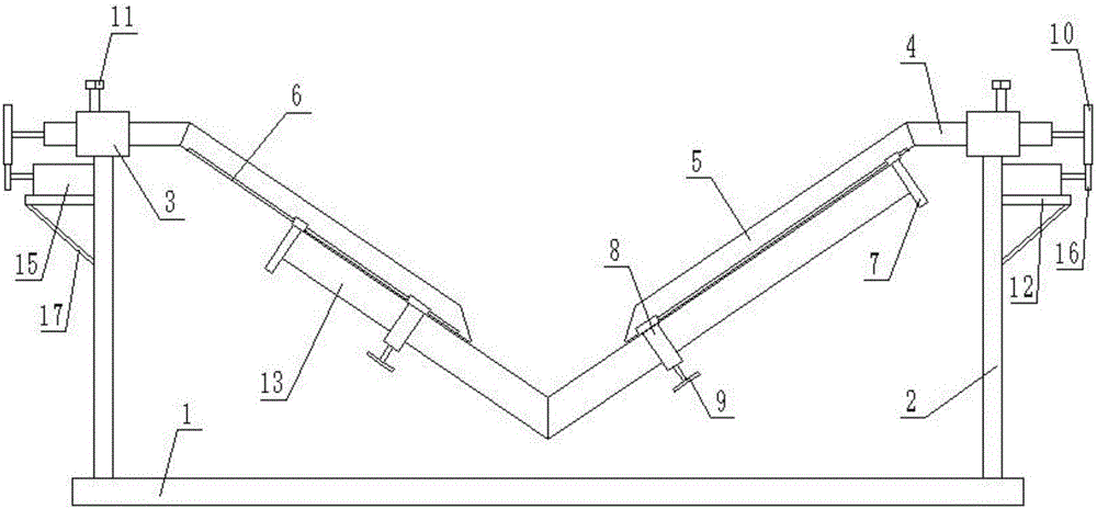
[0016] Such as Figure 1-2 As shown, the welding device for electric-driven reversible bending pipe fittings provided by the present invention includes a base 1, a column 2 is affixed to both sides of the top of the base 1, a shaft sleeve 3 is affixed to the top of the column 2, and the shaft sleeve 3 is inserted A rotating shaft 4 is installed, and the inner end of the rotating shaft 4 is fixedly connected with a seat plate 5 arranged obliquely. Slide rails 6 are installed on both sides of the top end of the seat plate 5, and sliding baffles 7 and 6 are respectively installed on the same seat plate 5 through the slide rails 6 The sliding clamping seat 8 is arranged at intervals between the left and right seat plates 5, the top of the sliding clamping seat 8 is equipped with a ...


PUM


Abstract

The invention discloses an electrically driven turnover welding device for bent pipes. The electrically driven turnover welding device for bent pipes comprises a base, wherein each of the two sides of the top end of the base is fixedly connected with one stand column, the top end of each stand column is fixedly connected with one shaft sleeve, one rotary shaft is installed in each shaft sleeve in an insertion manner, the end of the inner side of each rotary shaft is fixedly connected with one base plate which is arranged in an inclined manner, one sliding rail is installed on each of the two sides of the top end of each base plate, one sliding baffle and one sliding clamping base are installed on each base plate through the corresponding sliding rails respectively, one locking handle is installed at the top end of each sliding clamping base, one fixing rod is hinged to the bottom end of each locking handle, one locking screw matched with the corresponding rotary shaft is installed at the top end of each shaft sleeve, one rotary gear is fixedly connected with the end of each rotary shaft, one platform is fixedly connected with the outer side of each stand column, one motor is installed on each platform, and a driving gear meshed with the corresponding rotary gear is fixedly connected with the tail end of the output shaft of each motor. According to the electrically driven turnover welding device for bent pipes, the two base plates overturn through the rotary shafts driven by the motors, all the requirements of welding can be met without taking down a pipe, the pipe will not deform or be bent, and the qualification rate of finished products is increased.

Description

technical field [0001] The invention relates to the technical field of mechanical processing, in particular to the technical field of pipe fitting welding, and in particular to an electrically driven reversible welding device for bending pipe fittings. Background technique [0002] At present, in the field of welding, it is often necessary to weld bent pipes, that is, to splice two pipes together to form a specific angle between them, and then weld the two independent pipes into a whole by welding at the joint position of the two pipes For bent pipe fittings, the traditional welding method is mainly done manually, that is, the staff will splice the two pipe fittings to be welded together and clamp them with a simple fixture. The fixture is generally horizontally fixed, that is, the pipe fittings are horizontal Placed, after welding one side, you need to take out the pipe fittings and turn over to weld the other side. Obviously, the traditional welding method is not only time...

Claims


Application Information

Patent Timeline
IPC IPC(8): B23K37/047
CPCB23K37/047
Inventor 邱怀鸣方建平
Owner GUIZHOU ZUNYI CHI YU PRECISION MACHINERY MFG
Why Eureka
Try Eureka