Gap bridge track device and track transferring transporting vehicle group
A track group and track technology, which is applied in transportation and packaging, railway car body parts, railway couplings, etc., can solve the problems of cumbersome process and heavy weight of track connection devices, and achieve the effect of convenient disassembly and simple structure
- Summary
- Abstract
- Description
- Claims
- Application Information
AI Technical Summary
Problems solved by technology
Method used
Image

Examples
Embodiment 1
[0035] In view of the defect that the track connecting device in the prior art can only adapt to the curved track or the straight track with a radius greater than the preset value for the rail changing operation, this embodiment provides a bridge track connecting device, which can make the rail transport vehicle group adapt to the curved track Carry out track laying work.
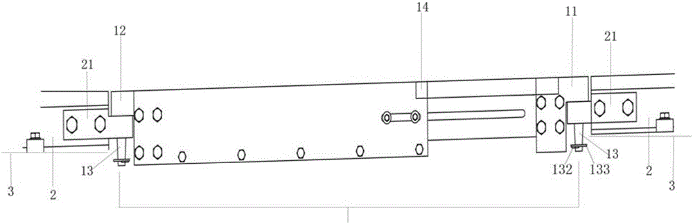
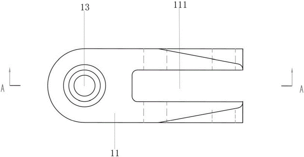
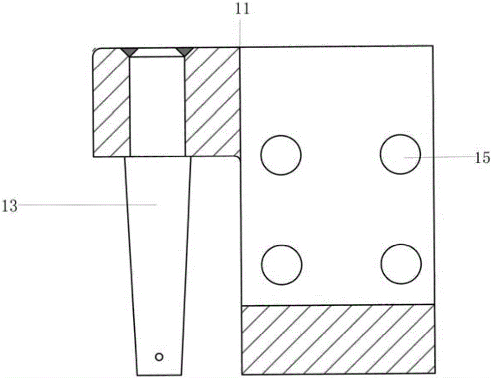
[0036] figure 1 It is a structural representation of the bridge track device of the embodiment; figure 2 It is a schematic top view structure diagram of the combination of the first connecting piece and the rotating shaft in this embodiment; image 3 It is a schematic diagram of the A-A sectional structure of the combination of the first connecting piece and the rotating shaft in this embodiment; Figure 4 It is a schematic top view structure diagram of the combination of the second connecting piece and the rotating shaft in this embodiment; Figure 5 It is a structural schematic diagram of the B-B sect...
Embodiment 2
[0043] Referring to the bridge track device provided in Embodiment 1, the difference is that there is no telescopic connection between the first connecting member 11 and the second connecting member 12, but the first connecting member 11 and the second connecting member The connecting piece 12 is directly connected. Since the first connecting piece 11 and the second connecting piece 12 are connected to the base 21 through the rotating shaft 13, and one end of the rotating shaft 13 is suspended, the first connecting piece 11 and the second connecting piece 12 directly correspond to each other through the bolt holes 14 and are fixed with bolts. connection, it can also be realized that there will be no interference between the rails 2 on the carriage 3 when the track-changing transport group travels on the traveling track with a radian. Can not pass through the travel track of smaller radian, the minimum radian of the travel track that can pass specifically is determined accordin...
Embodiment 3
[0045] Figure 6 For the structural schematic diagram of the telescopic part of the bridge track device provided in this embodiment, refer to Embodiment 2 and the provided bridge track device and Figure 6 , the difference is that the connecting device 1 further includes a telescopic piece 14 whose length in the horizontal direction can be changed, one end of the telescopic piece 14 is hinged to the first connecting piece 11 , and the other end of the telescopic piece 14 is hinged to the second connecting piece 12 . The connection device 1 designed in this way is more suitable for the situation that two rows of parallel rails 2 are arranged on the compartment 3 . When the track-changing transport vehicle group passes through the traveling track with radians, the compartment 3 and the compartment 33 must not travel in the same straight line, and the angle between the adjacent two compartments 3 is less than 180 degrees, generating an interior angle. The inner telescopic member...
PUM
 Abstract
Description
Claims
Application Information
 - R&D
- Intellectual Property
- Life Sciences
- Materials
- Tech Scout
- Unparalleled Data Quality
- Higher Quality Content
- 60% Fewer Hallucinations
Browse by: Latest US Patents, China's latest patents, Technical Efficacy Thesaurus, Application Domain, Technology Topic, Popular Technical Reports.
© 2025 PatSnap. All rights reserved.Legal|Privacy policy|Modern Slavery Act Transparency Statement|Sitemap|About US| Contact US: help@patsnap.com