Light steel house connecting structure

A technology for connecting structures and houses, which is applied in the direction of building components, building structures, and residential buildings. The effects of detachment, tight connection, and improved connection stability

Active Publication Date: 2016-10-26
ZHEJIANG FEIWU ARCHITECTURAL TECH CO LTD
View PDF7 Cites 3 Cited by
  • Summary
  • Abstract
  • Description
  • Claims
  • Application Information

AI Technical Summary

Problems solved by technology

[0004] This kind of prefabricated prefabricated protective shed has a simple structure. In daily use, when an earthquake occurs or a large transport vehicle passes by, a certain amount of vibration will be generated. This vibration is extremely easy to cause the above-mentioned bolts to loosen, resulting in The pre-embedded pipe and square steel loosened, causing the prefabricated prefabricated protective shed to fall apart

Method used


Image

  • Light steel house connecting structure
  • Light steel house connecting structure
  • Light steel house connecting structure

Examples


Embodiment 1

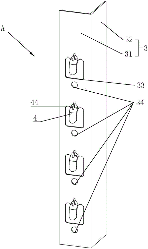
[0044] Embodiment 1: A connection structure of a light steel house, such as figure 1 and Figure 4 As shown, a supporting plate 3 and a fixing plate 5 are included. The support plate 3 is elongated and its length direction is set along the vertical direction, including an integrated connection part 32 and a mounting part 31. The width direction of 31 is arranged vertically.

[0045] Such as figure 1 and Figure 5 As shown, the end of the beam 1 is welded to the connecting portion 32 . Four support blocks 4 are integrally connected to the installation part 31 , and the four support blocks 4 are arranged along the length direction of the installation part 31 , and the distances between adjacent support blocks 4 are equal.

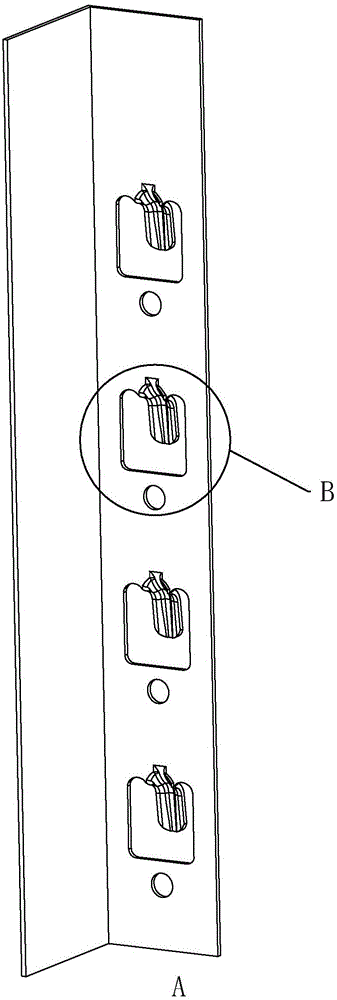
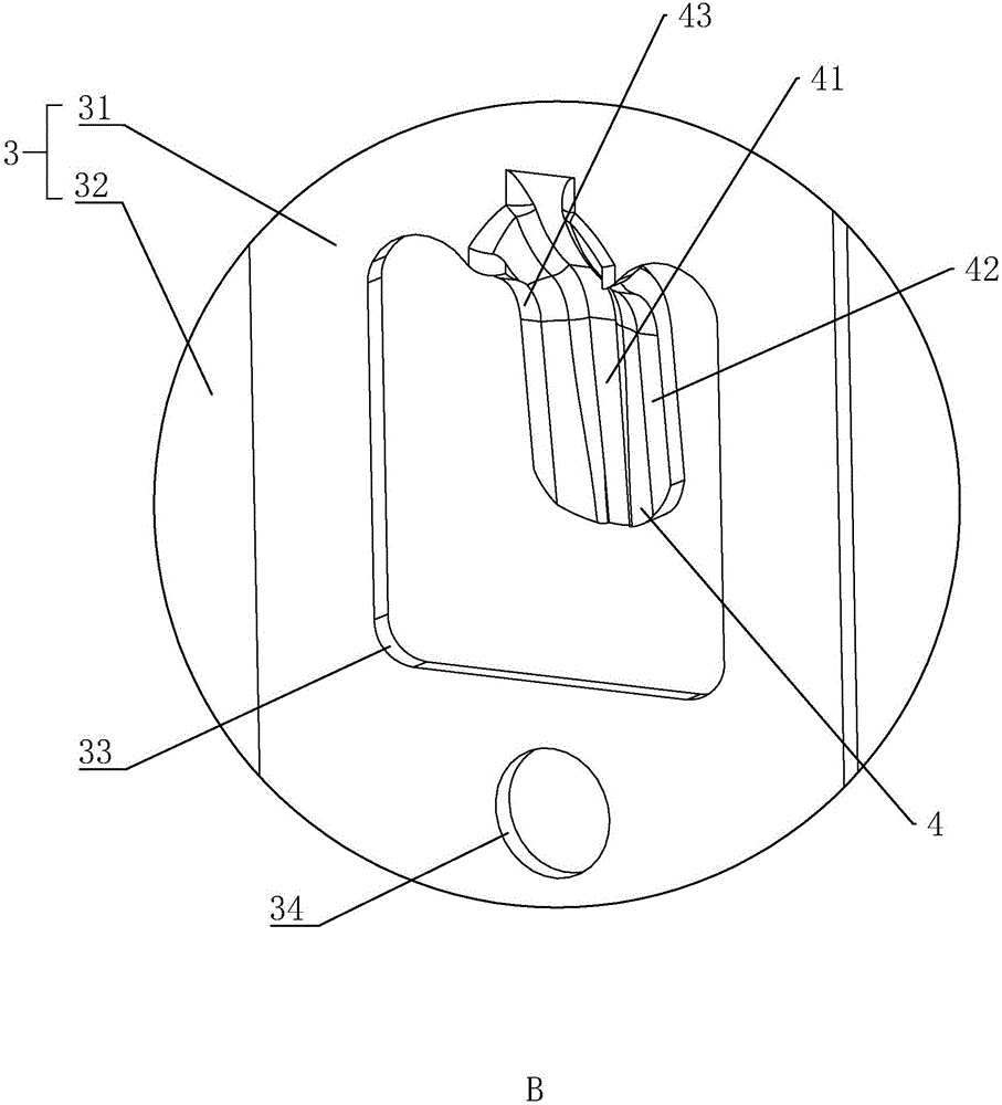
[0046] Such as figure 2 and image 3 As shown, one end of the support block 4 is connected to the installation part 31, and the other end is suspended. The end of the support block 4 away from the installation part 31 is inclined downward in the vert...

Embodiment 2

[0056] Embodiment 2: A connection structure of a light steel house, such as Figure 10 to Figure 13 As shown, the difference with embodiment 1 is that the fixed plate 5 is removed (see Figure 6 )setting.

[0057] Such as Figure 11 and Figure 12 As shown, the column 2 is a hollow quadrangular prism, and each face of the column 2 is provided with sixteen fixing holes 53 and the second positioning holes 52, see Figure 10 , with eight fixing holes 53 and the second positioning hole 52 as a group, which are respectively placed at the upper and lower ends of the column 2, see Figure 11 , the four fixing holes 53 and the second positioning holes 52 in each group form a row, that is, the end of each column 2 is provided with two rows of fixing holes 53 and the second positioning holes 52, and the fixing holes 53 and the second positioning holes of each row The positioning holes 52 are arranged along the length direction of the column 2 .

[0058] As described in Embodiment 1...


PUM


Abstract

The invention discloses a light steel house connecting structure. The problem that a cross beam and a stand column are likely to loosen to fall apart is solved. According to the technical scheme, the light steel house connecting structure is characterized by comprising a supporting plate and a fixed plate; the supporting plate is fixedly connected with a cross beam, the fixed plate is fixedly connected with a stand column, the supporting plate is integrally connected with a supporting block, one end of the supporting block is connected with the supporting plate, and the other end of the supporting block extends in the direction away from the supporting plate and is inclined in the vertical direction; a fixed hole is formed in the fixed plate and comprises two opposite inclined faces, a containing groove abutting against the supporting block is formed by the two inclined faces, and the supporting block is placed in the containing groove. The aim of preventing the cross beam and the stand column from loosening is achieved.

Description

technical field [0001] The invention relates to a connection structure of a light steel house. Background technique [0002] In the construction industry, workers often build prefabricated houses by themselves for living. [0003] At present, the Chinese patent whose publication number is CN105780929A discloses a kind of prefabricated house assembled protective shed, which includes a roof and four vertical mechanisms, and the roof is erected above the four vertical mechanisms; the vertical mechanisms include A square steel, a pre-embedded pipe, a round steel pipe and a concrete base, the square steel is detachably fixed on the concrete base; the pre-embedded pipe is located inside the square steel, the top and bottom of the pre-embedded pipe The upper steel sheet and the lower steel sheet are respectively welded at the ends, and the upper steel sheet and the lower steel sheet are respectively welded to the square steel; the round steel pipe passes through the upper steel sh...

Claims


Application Information

Patent Timeline
Patent Type & Authority Applications(China)
IPC IPC(8): E04B1/58E04B1/24
CPCE04B1/2403E04B2001/2412E04B2001/2415E04B1/5831E04B2001/2409E04B2/58E04B2001/246E04H1/02
Inventor 黄峻吴怀东
Owner ZHEJIANG FEIWU ARCHITECTURAL TECH CO LTD
Why Eureka
Try Eureka